Note:
Before starting configuration, a new module instance must be created. Click here for more information about creating Module instances.
Module Configuration
.png)
As shown in the previous screenshot, multiple connections can be created in the Model Panel by clicking on the burger menu icon. The drop-down menu shows 4 different connection options:
TcpClient
TcpServer
UdpClient
UdpServer
See below for an explanation of the different configuration options.
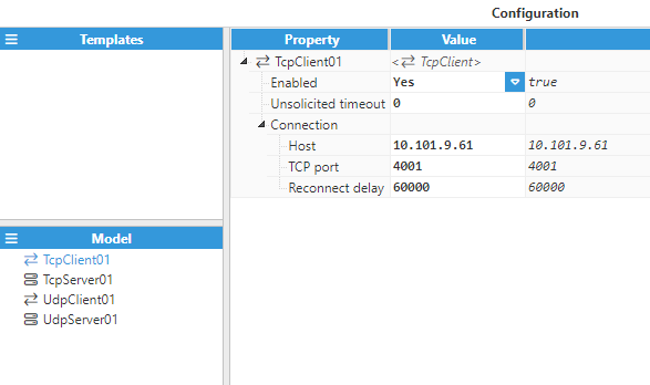
TcpClient
TcpClient has the following configuration options:
Enabled: When disabled, the channel will remain inactive. The default value is set to Enabled.
Unsolicited Timeout: Maximum time for receiving an unsolicited update of the value before the tag quality is changed to bad quality, displayed in milliseconds. The default value is 0, which means Unsolicited Timeout is deactivated.
Connection:
Host: Hostname or IP address of the target device.
TCP port: Determines which TCP Port to connect to. Valid values range from 1 to 65535.
Reconnect delay:Time before attempting to re-open the connection after a failed attempt, displayed in milliseconds. The minimum value is 1,000ms.
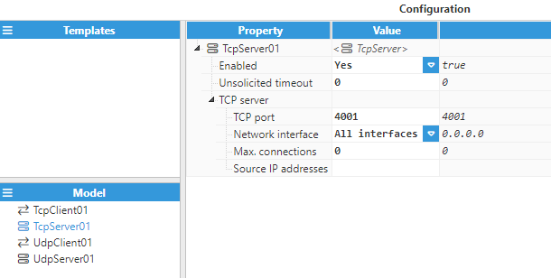
TcpServer
TcpServer offers the following configuration options:
Enabled: When disabled, the channel will remain inactive. The default value is set to Enabled.
Unsolicited Timeout: Maximum time for receiving an unsolicited update of the value before the tag quality is changed to bad quality, displayed in milliseconds. The default value is 0, which means Unsolicited Timeout is deactivated.
TCP Server:
TCP port: TCP port for incoming connections. The valid range is 1 to 65535, the default port number is 4001. This port may not be used by any other applications running on the same machine.
Network interface: Specifies which interface the TCP Server will be accessible from. If set to All interfaces, the TCP Server will listen to connections on all interfaces. If set to Localhost only, the TCP Server will only listen to localhost connections. In addition to the above options, the IP address for a specific network interface can also be set to only allow connections from its own network.
Max connections: The maximum number of TCP clients supported by this server. Set to 0 to disable the limit.
Source IP addresses: Allows IP addresses to be whitelisted for incoming connections. Several IP addresses can be permitted using a comma-separated list. No restrictions are applied when left empty.
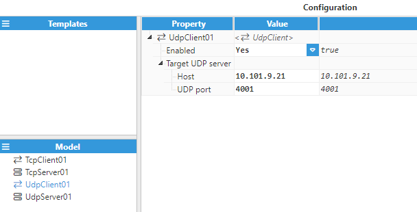
UdpClient
UdpClient has the following configuration options:
Enabled: When disabled, the channel will remain inactive. The default value is set to Enabled.
Target UDP Server:
Host: Hostname or IP address of the target device.
UDP port: Determines which UDP port to connect to. Valid values range from 1 to 65535.
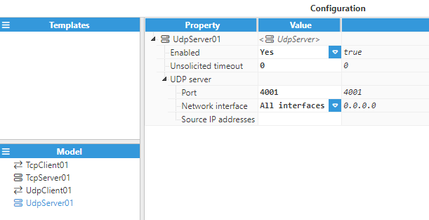
UdpServer
UdpServer has the following configuration options:
Enabled: When Disabled, the channel will remain inactive. The default value is set to Enabled.
Unsolicited Timeout: Maximum time for receiving an unsolicited update of the value before the tag quality is changed to bad quality, displayed in milliseconds. The default value is 0, which means Unsolicited Timeout is deactivated.
UDP Server:
TCP port: TCP port for incoming connections. The valid range is 1 to 65535, the default port number is 4001. This port may not be used by any other applications running on the same machine.
Network interface: Specifies the interface via which the UDP Server will be accessible. If set to All interfaces, the UDP Server will listen to connections on all interfaces. If set to Localhost only, the UDP Server will only listen to localhost connections. In addition to the above options, the IP address for a specific network interface can also be set to only allow connections from its own network.
Source IP addresses: Allows IP addresses to be whitelisted for incoming connections. Several IP addresses can be permitted using a comma-separated list. No restrictions are applied when left empty.
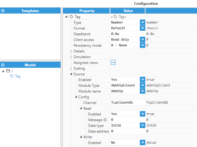
Tag Configuration
Once the connection has been configured, users will be able to create and configure as many tags as required.
Tags require the following parameters to be configured:
Source
Enabled: When disabled, tags will not be updated with the values received from the device, but instead, will essentially act as memory tags. When set to Enabled, the tag value will be continuously updated with the values received from the field device. The default value is set to Disabled.
Module type: Defines the driver type used to retrieve values from the field. In this example, AbbVipClient must be selected from the drop-down menu. If AbbVipClient does not appear in the drop-down menu, it means that this driver has not yet been installed on this machine and therefore, must be installed.
Module name: Introduce the name of the previously created ABB VIP Client module instance.
Config
Channel: Introduce the name of the communication channel used to exchange data with the target device. This channel must have been created and configured in the ABB VIP Client module instance.
Read:
Enabled: Enable or disable data collection.
Message ID: Specifies the ID of the message that contains the tag value. The valid range is 0 to 65535.
Data type: Specifies the type of data received:
Int16: Integer 16 bits (2 Bytes).
Int32: Integer 32 bits (4 Bytes).
Float 32: IEEE754 Single Precision (4 Bytes).
String (Format 1): ASCII String according to Format 1 in the protocol specification. The length of the string is specified in the Data address parameter.
Data address: Position of the value inside the data frame. It starts at 0 and is expressed in bytes. Bits within integers are referred to as <position>:<bit> (Bit from 0 to 15). Strings are referred to as <position>:<length> (length in bytes from 0 to 255). For example: Bit 0 within an Int16 at position 20 of the frame: Data address= 20.0 .
Write
Enabled: Enable or disable write operations. When enabled, the value of this tag will be included in the message sent from this device to other devices.
Message ID: Specifies the ID of the message that contains the tag value. The valid range is 0 to 65535.
Data type: Specifies the type of data received:
Int16: Integer 16 bits (2 Bytes).
Int32: Integer 32 bits (4 Bytes).
Float 32: IEEE754 Single Precision (4 Bytes).
String (Format 1): ASCII String according to Format 1 in the protocol specification.
Trigger: Every write message must include a boolean tag that will act as a trigger to send the message. When the value of the tag defined as Trigger changes to true, the message is sent, including the current values of the tags associated with the message. Once the message has been sent, the tag used as a Trigger is automatically reset to false.
The image below shows the tag configuration parameters.