Note
Before starting configuration, a new module instance must be created. Click here for more information about creating Module instances.
Module Configuration
.png)
As shown in the previous screenshot, multiple connections can be created in the Model Panel by clicking on the burger menu icon. Each connection is named Channel. See below for an explanation of the different configuration options.
Channel Configuration
A channel represents the physical medium of connecting one or more devices. Each channel object has the following configuration options:
Enable data collection: When disabled, the channel will remain inactive. The default value is set to Enabled.
Timing
Request Timeout: Maximum amount of time to wait for a valid response, displayed in milliseconds. The valid range is 100ms to 600,000ms. The default value is set to 3,000ms.
Retry attempts: Number of communication retries before considering the target device as unreachable. The valid range is 0 to 100. The default value is 3.
Inter-request delay: Delay before sending the next request to the target device, displayed in milliseconds. The valid range is 0ms to 600,000ms. The default is 0ms.
Connection:
Type: Specifies the connection type that will be established:
TCP: TCP socket.
Serial: Serial Port.
When connecting through TCP, the following options are displayed:
Config:
Host: Hostname or IP address of the target device.
TCP port: Sets the TCP Port to connect to during communication. Valid values range from 1 to 65535. The default value is 4001.
Reconnect delay: Time before trying to re-open the connection after a failed attempt, displayed in milliseconds. The minimum value is 1,000ms.
.png)
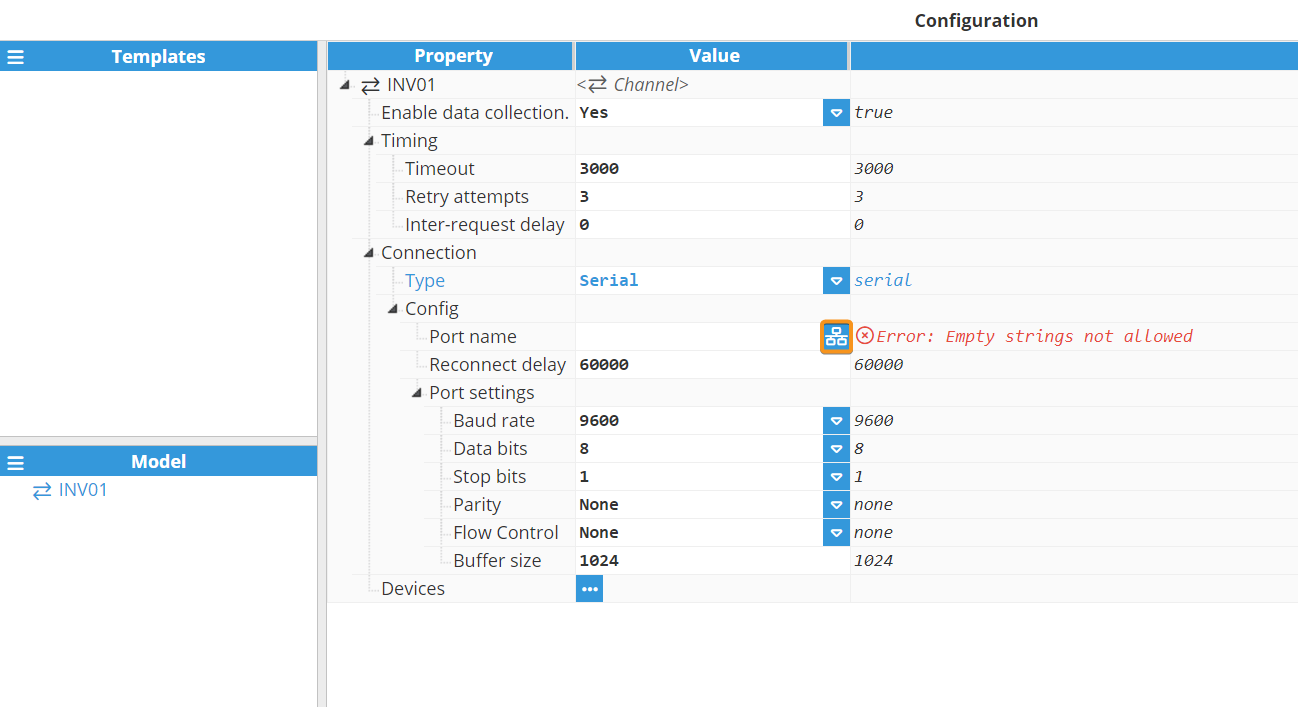
Serial channels have the following available options:
Config:
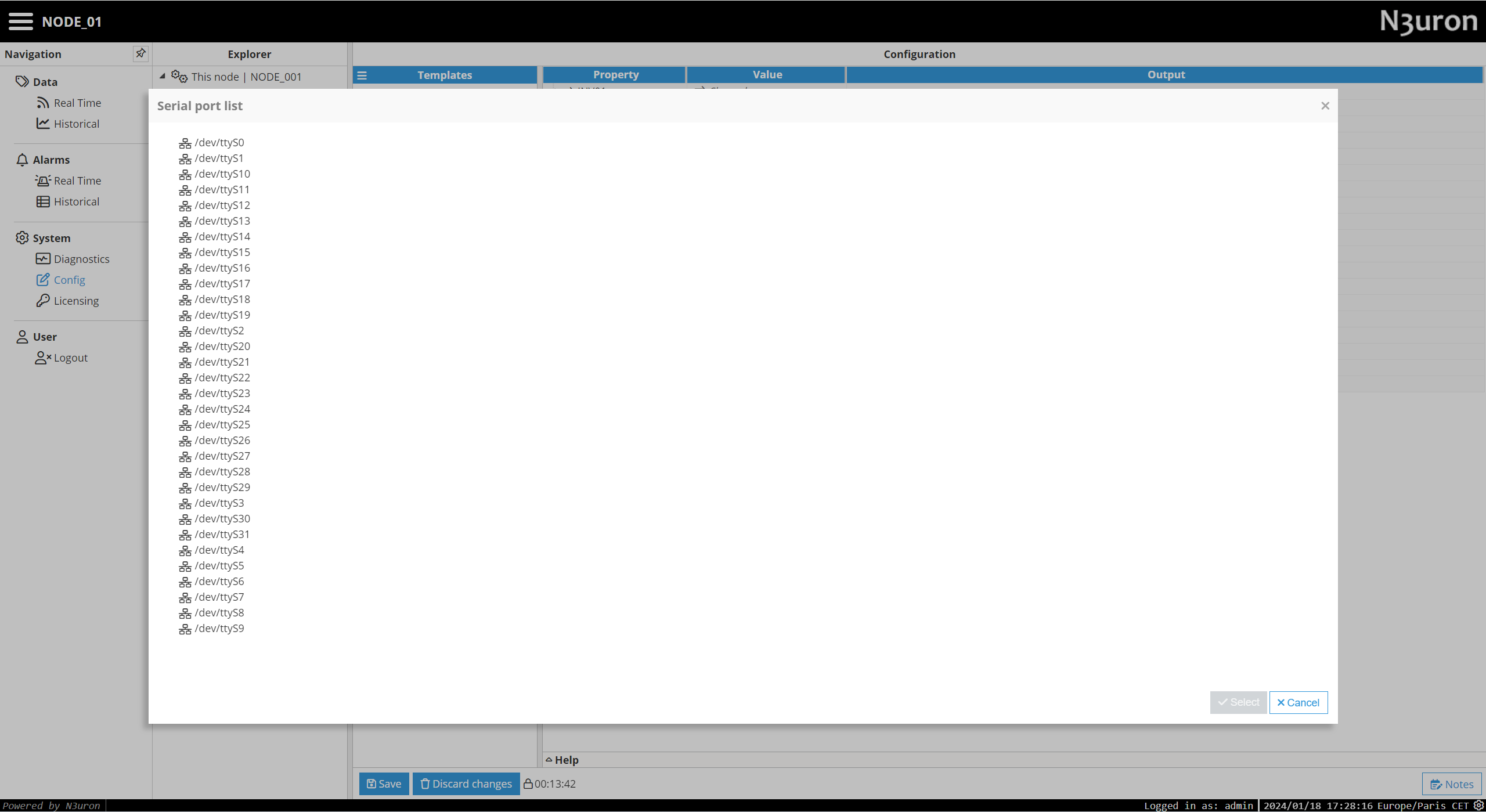
Port name: Serial port as displayed by the operating system. For example, if N3uron is running on Windows, valid port names would be COM1, COM2, and so forth, whilst if running on Linux, valid port names would be /dev/ttyS0, /dev/ttyS1, etc.
Note:
The dropdown menu for serial port selection is available from N3uron version V1.21.7 onwards
Reconnect delay: Time before trying to re-open the serial port after a failed attempt, displayed in milliseconds. The minimum value is 1,000ms.
Port settings:
Baud rate: Serial port transfer speed in milliseconds. Valid values are 110, 300, 1,200, 2,400, 4,800, 9,600, 19,200, 38,400, 57,600, or 115,200. The default is 9600.
Data bits: Specifies the number of data bits per data word. Valid values are 5, 6, 7, or 8.
Stop bits: Specifies the number of stop bits per data word. Valid values are 1 or 2.
Parity: Specifies the parity type for data. Valid values are None, even, mark, odd, or space.
Flow Control: Enables the use of RTS and DTR control lines. There are 3 options: None, RTS/CTS (RS232), and RTS (RS485/RS422).
Buffer size: Specifies the Serial communication buffer capacity. The valid range is 128 to 65,536. The default value is 1,024.
The image below shows an example serial channel configuration: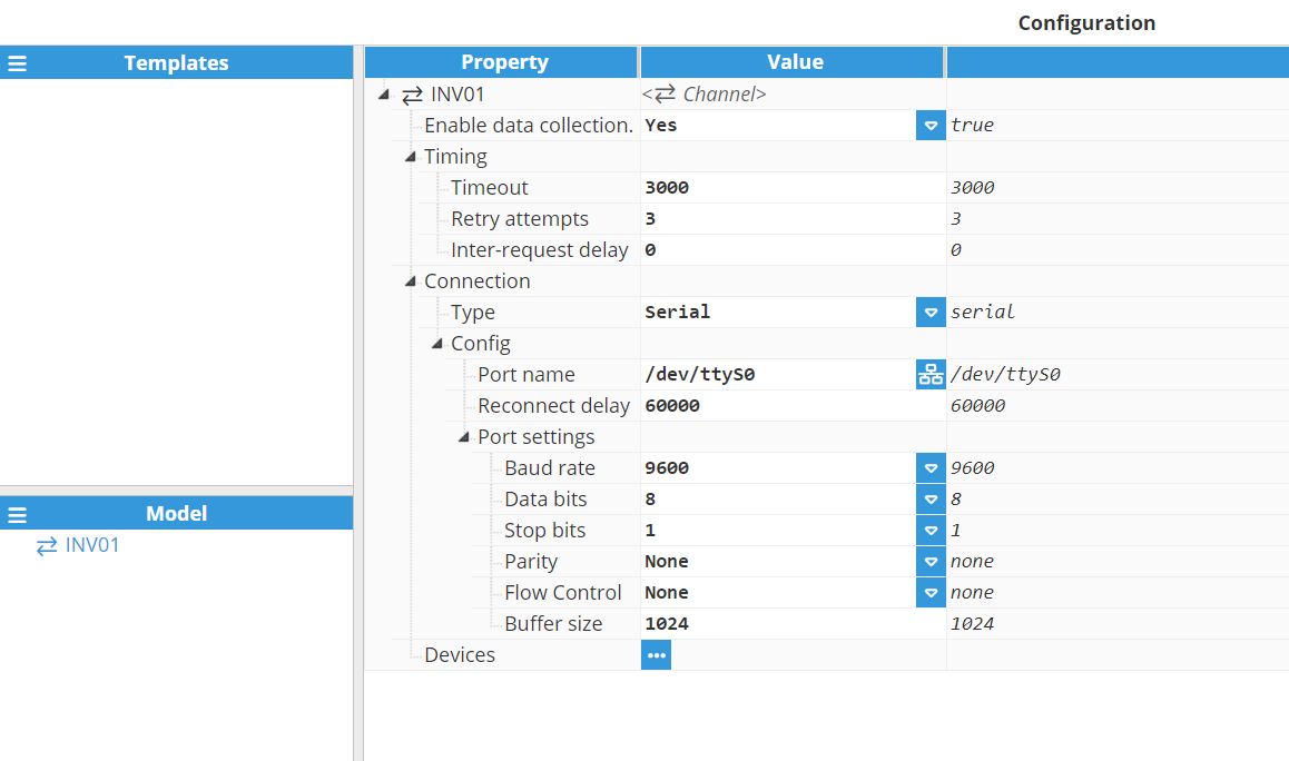
Device Configuration
Each channel can have one or more devices associated to it. A typical example of a channel containing a single device would be a direct TCP or serial connection to an Aurora slave. An example of multiple devices in the same channel would be when Aurora slaves are connected within the same serial bus.
.png)
Set a name for the device and proceed with the configuration. In this example, the device name is Device01.
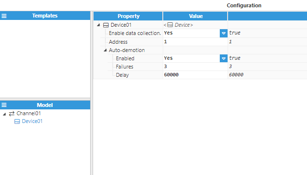
The configuration parameters are as follows:
Enable data collection: When Disabled, the channel will remain inactive. The default value is set to Enabled.
Address: Specifies the address that is assigned to the device.
Auto-demotion: Defines whether a device should be temporarily placed as “off-scan” when the device is not responding. If set to “off-scan”, read requests will not be sent to the device and any data associated with these read requests will automatically be set to “bad quality”. By placing a non-responsive device offline for a specified time period, the driver can continue to optimise its communications with other devices in the same channel. Once this demotion period has been reached, the driver will re-attempt to communicate with the non-responsive device. If the device is responsive, it will be placed as “on-scan”; otherwise, the off-scan time period will be restarted.
Enabled: When set to enabled, the device will automatically be taken “off-scan” until it starts to respond again.
Failures: Specifies the number of successive failures required before demoting the device. The minimum value is 1 and the default value is 3.
Delay: Determines the demotion period and indicates how long the device should be placed “off-scan” when the value of the failure has been reached. When the specified period expires, the driver will place the device as “on-scan” and allow another communication attempt to be made. The minimum value is 1,000. The default value is 60,000 milliseconds.
At this point, the connection is ready to go. However, users will still need to define a tag that will be used to select the different groups of variables to be retrieved from the device.
Tag Configuration
The channel and device configuration fields define the settings used when establishing connections to Aurora devices. After configuring these elements, users will be able to create and configure any tags associated with the data received from Aurora devices. Each device can have multiple associated tags, which will allow different types of information to be extracted, depending on the group and variable selected. The following image shows an example configuration:
.png)
The only mandatory settings that need be configured are those contained within the source section. These parameters are listed below:
Source
Enabled: If Enabled, this permits reading of tags from its source.
Module type: Select the module type that will become the tag source.
Module name: Introduce the name of the module previously created to work as a source for the tag.
Config
Device: Specify the device that was previously created to work as a slave for this connection. The format must be Channel/Device.
Scan rate: Poll interval for the specified tag, displayed in milliseconds. The minimum value is 100ms. Only applicable when the device mode is set to static polling.
Group: Select the group of variables to be collected from the device.
Variable: Select the variable to read from the previously selected group.
The different groups of variables supported by this module are listed in the below table:
Number | Function |
50 | State reading |
52 | P/N reading |
58 | Version reading |
59 | Measure request |
63 | Serial number request |
67 | Flags reading |
68 | Cumulated reading |
70 | Time/Date reading |
78 | Cumulated energy reading |
105 | System P/N reading |
107 | System serial number reading |
200 | Junction Box state request |
201 | Junction Box value request |
Note
When working with a Junction box, the junction box number needs to be specified when reading junction box states or values.