CAISO ADS Client Configuration
Step 1: Access the Configuration Interface.
Log in to your N3uron node using your credentials. By default username: admin and password: n3uron.
.png)
In the navigation panel on the left, under the System section, click on Config to access configuration settings.
Expand the Modules section in the Explorer and select the CaisoAdsClient instance.
In the Model panel, locate the connection configuration named ADS, which is used to connect to the CAISO ADS Host.
.png)
Step 2: CAISO ADS Connection Configuration.
Resource ID
Enter the plant Resource ID provided by CAISO. This specifies which resource the client will process data for.
Host URL and Port
Default Host URL:
https://adsws.prod.caiso.com/ADS/APIWebService/v8.Default Port:
443(for secure HTTPS connections).
Authentication
Upload the Certificate and provide the Passphrase supplied by CAISO.
These settings are essential for getting started. For advanced configuration details, refer to the CAISO ADS Client Configuration Guide.
OPC UA Server Configuration
Step 1: Data Model Sharing.
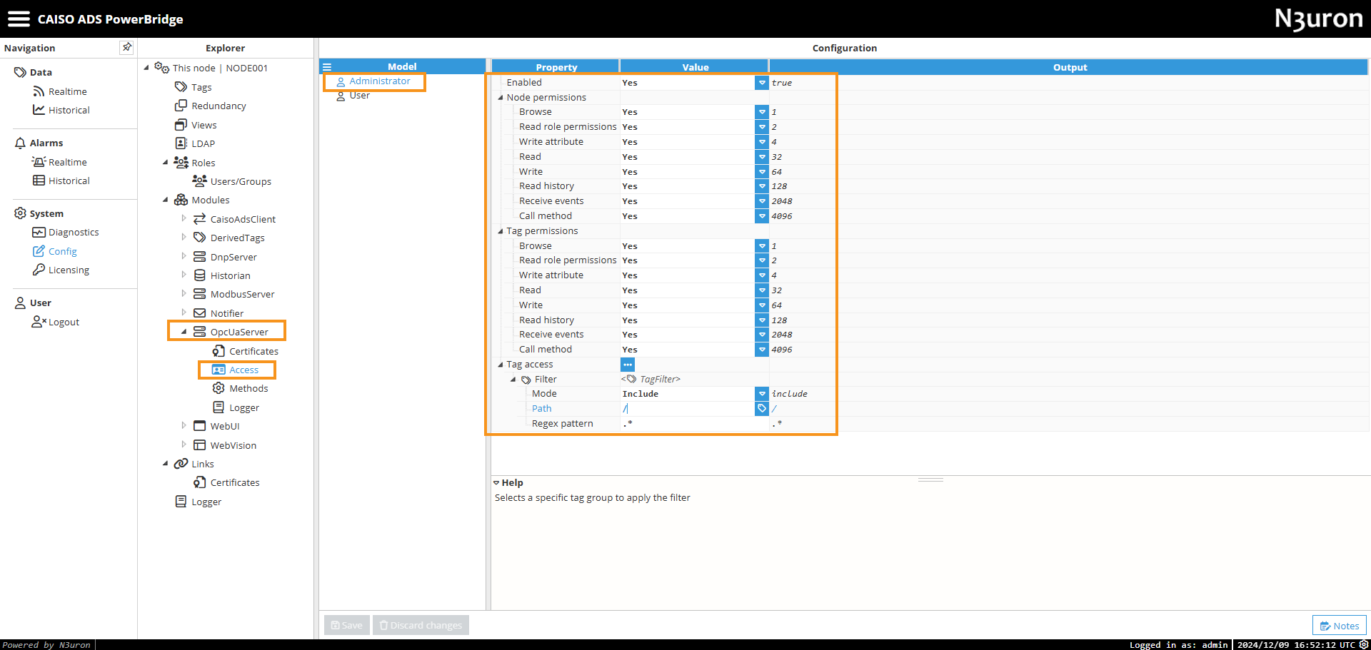
By default, the CAISO ADS PowerBridge shares its entire data model through the OPC UA Server. Access is managed using the Administrator predefined role, configured in the server's Access section of the OPC UA Server. Filters are applied for each role to determine which parts of the data model are accessible, allowing you to customize data visibility and permissions as needed. The Administrator role is granted full access permissions, providing access to the entire data model.
Note:
You can create new roles and users in the Roles section and assign them specific permissions to tailor access according to your operational requirements.
Step 2: Network Configuration.
Network interface: Use the Network Interfaces selector to select the appropriate NIC for your node.
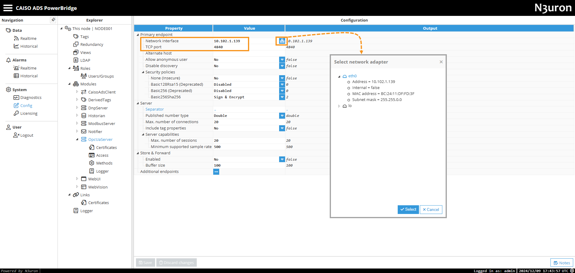
TCP Port: The OPC UA Server uses port 4840 by default.
Note:
Make sure this port is open and unrestricted by firewalls to ensure proper communication between the OPC UA Server and its clients.
Security policies:
The server’s security policy is configured to Sign and Encrypt communications using the Basic256Sha256 encryption method.
Anonymous access is disabled. Therefore, a valid username and password must be provided to establish a connection with the server.
All remaining settings are configured with default values. For more detailed information, refer to the OPC UA Server Configuration documentation.
DNP Server Configuration
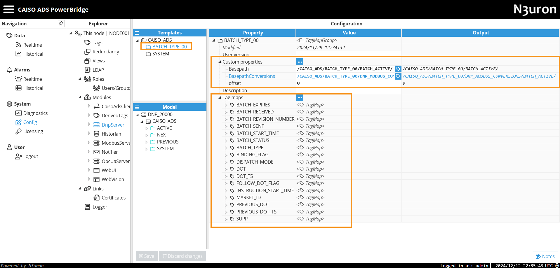
The DNP Server is preconfigured for immediate operation without requiring any modifications. However, if needed, you can adjust its settings, including the network interface, slave address, and master address. For more details, refer to the DNP Server Configuration section. Next, we will provide a detailed explanation of the DNP Server mapping.
.png)
BATCH_TYPE_00 Template
Custom Properties
Basepath: Specifies the base path to the tags within
BATCH_ACTIVE,BATCH_NEXT, andBATCH_PREVIOUSin the data model.BasepathConversions: Specifies the base path to the tags within
DNP_MODBUS_CONVERSIONS/BATCH_ACTIVE,BATCH_NEXT, andBATCH_PREVIOUSin the data model.Offset: Adjusts the DNP data point index by a specific value. The offset varies depending on whether it applies to the Active, Next, or Previous batches.
Tags Mapping
NAME | GROUP | VARIATION | INDEX | DESCRIPTION |
|---|---|---|---|---|
BINDING_FLAG | 01: Binary input | 2: 8-bit with flag | 2+offset | Flag indicating whether the batch is binding (Y) or non-binding(empty). |
FOLLOW_DOT_FLAG | 01: Binary input | 2: 8-bit with flag | 3+offset | Indicates whether the system should follow the ramp dots provided in the batch if 'Y'. |
MARKET_ID | 30: Analog input | 1: 32-bit with flag | 0+offset | Identifier for the market type. |
BATCH_REVISION_NUMBER | 30: Analog input | 1: 32-bit with flag | 1+offset | Integer representing the version of the batch. |
BATCH_EXPIRES | 30: Analog input | 1: 32-bit with flag | 2+offset | Timestamp in epoch (seconds) indicating when the batch is no longer valid. |
BATCH_RECEIVED | 30: Analog input | 1: 32-bit with flag | 3+offset | Timestamp in epoch (seconds) when the batch was received. |
BATCH_SENT | 30: Analog input | 1: 32-bit with flag | 4+offset | Timestamp in epoch (seconds) indicating when the batch was sent. |
BATCH_START_TIME | 30: Analog input | 1: 32-bit with flag | 5+offset | The start time in epoch (seconds) for the batch's effective period. |
INSTRUCTION_START_TIME | 30: Analog input | 1: 32-bit with flag | 6+offset | Start time of the dispatch instruction. |
BATCH_STATUS | 30: Analog input | 2: 16-bit with flag | 7+offset | Indicates the current status of the batch, represented by predefined numerical codes. |
BATCH_TYPE | 30: Analog input | 2: 16-bit with flag | 8+offset | Type or category of the batch. |
DISPATCH_MODE | 30: Analog input | 2: 16-bit with flag | 9+offset | Mode of dispatch for the batch (0 = Interval 1 = Manual 2 = Contingency). |
DOT | 30: Analog input | 5: 32-bit floating-point with flag | 10+offset | Dispatch Operational Target (MW). |
DOT_TS | 30: Analog input | 1: 32-bit with flag | 11+offset | Timestamp in epoch (seconds) for Dispatch Operational Target (MW). |
PREVIOUS_DOT | 30: Analog input | 5: 32-bit floating-point with flag | 12+offset | Previous Dispatch Operational Target (MW). |
PREVIOUS_DOT_TS | 30: Analog input | 1: 32-bit with flag | 13+offset | Timestamp in epoch (seconds) for Previous Dispatch Operational Target (MW). |
SUPP | 30: Analog input | 5: 32-bit floating-point with flag | 14+offset | Supplemental Energy instruction value (MW). |
SYSTEM Template
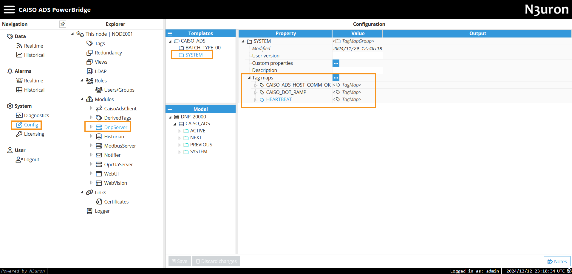
Tags Mapping
NAME | GROUP | VARIATION | INDEX | DESCRIPTION |
|---|---|---|---|---|
HEARTBEAT | 01: Binary input | 2: 8-bit with flag | 0 | System Heartbeat |
CAISO_ADS_HOST_COMM_OK | 01: Binary input | 2: 8-bit with flag | 1 | Status of Comm. with CAISO ADS Host. |
CAISO_DOT_RAMP | 30: Analog input | 5: 32-bit floating-point with flag | 15 | Ramp to reach the DOT (MW). |
Modbus Server Configuration
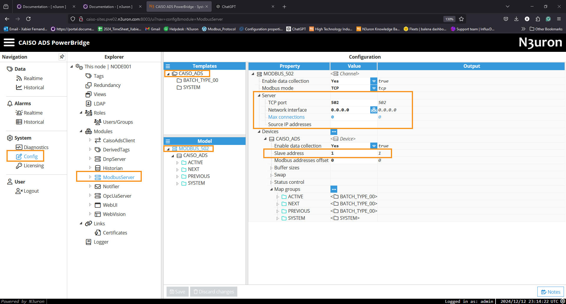
The Modbus Server is preconfigured to operate immediately without requiring any modifications. However, if needed, you can adjust its settings, including the network interface and the slave addresss. For more details, refer to the Modbus Server Configuration section. Next, we will provide a detailed explanation of the Modbus Server mapping.
BATCH_TYPE_00 Template
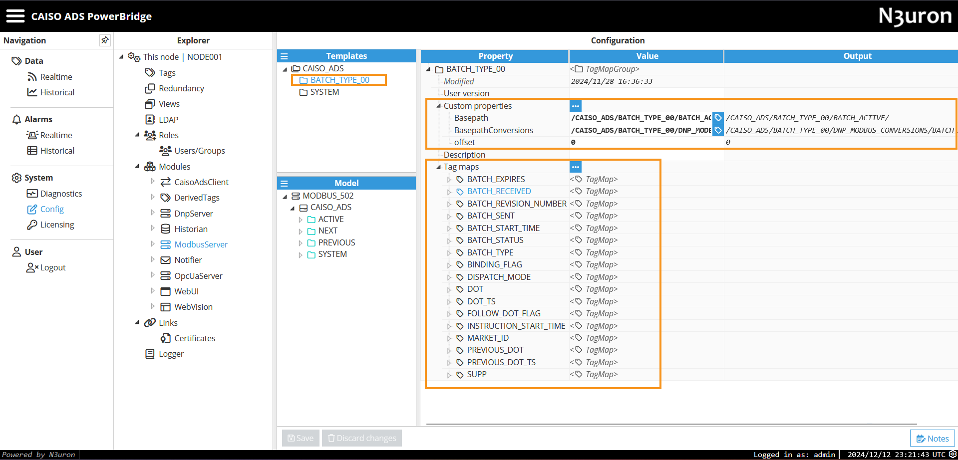
Custom Properties
Basepath: Specifies the base path to the tags within
BATCH_ACTIVE,BATCH_NEXT, andBATCH_PREVIOUSin the data model.BasepathConversions: Specifies the base path to the tags within
DNP_MODBUS_CONVERSIONS/BATCH_ACTIVE,BATCH_NEXT, andBATCH_PREVIOUSin the data model.Offset: This property specifies the offset value to be added automatically to all Modbus addresses. This offset varies depending on whether it applies to the Active, Next, or Previous batches.
Tags Mapping
NAME | DATA TYPE | ADDRESS | DESCRIPTION |
|---|---|---|---|
BINDING_FLAG | BOOL | 300001.2+offset | Flag indicating whether the batch is binding (Y) or non-binding(empty). |
FOLLOW_DOT_FLAG | BOOL | 300001.3+offset | Indicates whether the system should follow the ramp dots provided in the batch if 'Y'. |
MARKET_ID | UINT16 | 300002+offset | Identifier for the market type. |
BATCH_REVISION_NUMBER | UINT16 | 300003+offset | Integer representing the version of the batch. |
BATCH_EXPIRES | UINT32 | 300004+offset | Timestamp in epoch (seconds) indicating when the batch is no longer valid. |
BATCH_RECEIVED | UINT32 | 300008+offset | Timestamp in epoch (seconds) when the batch was received. |
BATCH_SENT | UINT32 | 300012+offset | Timestamp in epoch (seconds) indicating when the batch was sent. |
BATCH_START_TIME | UINT32 | 300016+offset | The start time in epoch (seconds) for the batch's effective period. |
INSTRUCTION_START_TIME | UINT32 | 300020+offset | Start time of the dispatch instruction. |
BATCH_STATUS | UINT16 | 300021+offset | Indicates the current status of the batch, represented by predefined numerical codes. |
BATCH_TYPE | UINT16 | 300022+offset | Type or category of the batch. |
DOT | FLOAT32 | 300026+offset | Dispatch Operational Target (MW). |
DOT_TS | UINT32 | 300030+offset | Timestamp in epoch (seconds) for Dispatch Operational Target (MW). |
PREVIOUS_DOT | FLOAT32 | 300034+offset | Previous Dispatch Operational Target (MW). |
PREVIOUS_DOT_TS | UINT32 | 300038+offset | Timestamp in epoch (seconds) for Previous Dispatch Operational Target (MW). |
SUPP | FLOAT32 | 300042+offset | Supplemental Energy instruction value (MW). |
SYSTEM Template
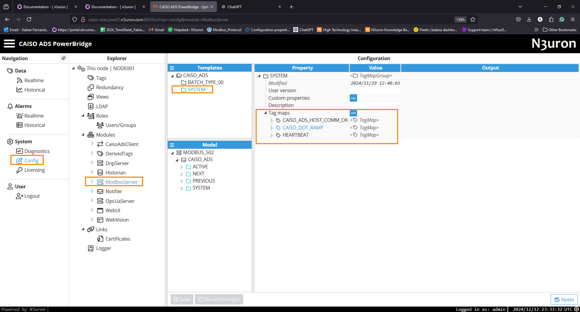
Tags Mapping
NAME | DATA TYPE | ADDRESS | Description |
|---|---|---|---|
HEARTBEAT | BOOL | 300001.0 | System Heartbeat |
CAISO_ADS_HOST_COMM_OK | BOOL | 300001.1 | Status of Comm. with CAISO ADS Host. |
CAISO_DOT_RAMP | FLOAT32 | 300046 | Ramp to reach the DOT (MW). |
Notifier Module Configuration
.png)
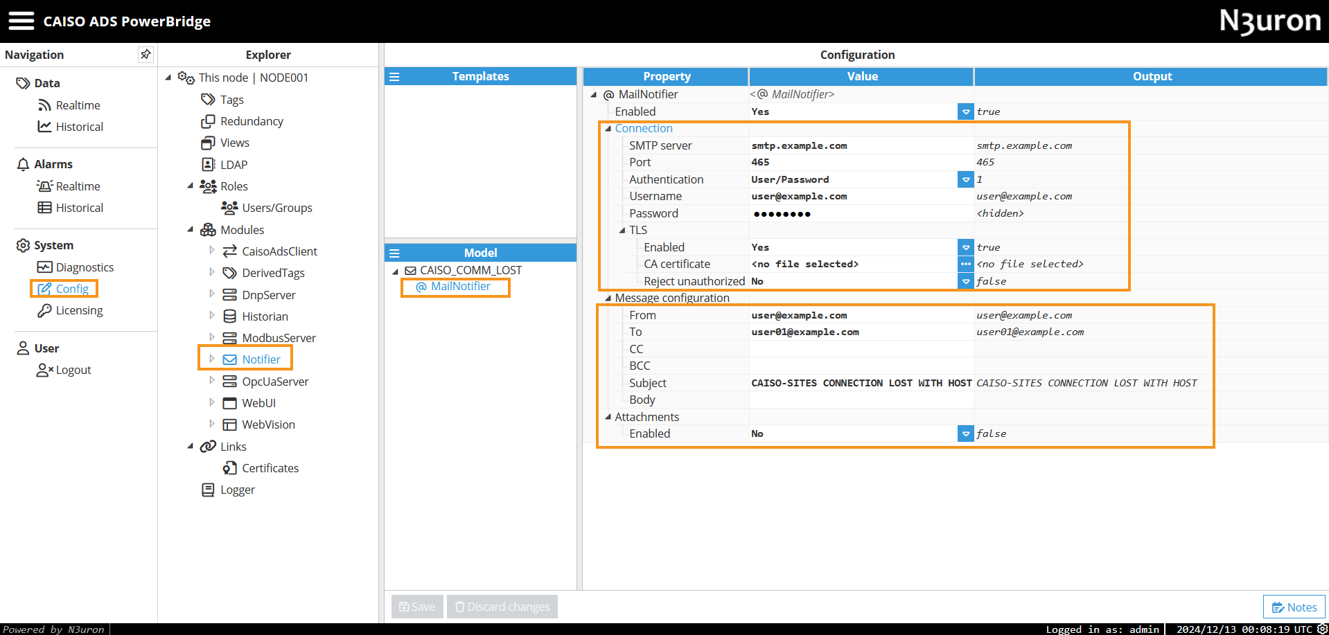
The Notifier module is preconfigured to send an email notification when the CAISO_ADS_HOST_COMM_OK tag alarm is triggered, with a delay of 3000ms. This alarm notifies recipients about a connection loss with the CAISO ADS Host.
While the Notifier module can also be configured to send notifications via SMS, this feature is not enabled by default. By default, email notifications are sent when the alarm is either Active and unacknowledged or Active and acknowledged. For detailed information on configuring the Notifier module, refer to the Notifier Configuration section.
Trigger Configuration
The CAISO_ADS_HOST_COMM_OK tag alarm is preconfigured in the data model for this purpose.
.png)
Mail Notifier
The Connection and Message configuration settings for the Mail Notifier are shown below. Ensure the SMTP server settings are adjusted to meet your specific requirements.
