Sending data from one N3uron node to another via the Data Diode
In this example, the Data Diode module has been used to send data, in a unidirectional way, from a sending N3uron node to a receiving N3uron node.
Configuring the sending node:
- Step 1: Add a new module in the “Modules” section, name it, and select “DataDiode” in the “Module type” field.
.png)
- Step 2: Configure the Logger and API for the Data Diode module. In this example, the default configuration settings have been left unedited, since (in most cases) this a valid configuration option.
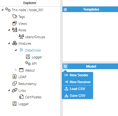
- Step 3: Add a new Sender within the “Model” section and choose a name for it.
.png)
- Step 4: Configure the Sender (Host, UDP port, etc.) and save the changes. In this example, data is sent without encryption to another N3uron node with the following IP address: 10.101.3.31.
.png)
Configuring the receiving node:
- Step 5: Add a new module in the “Modules” section, give it a name, and select “DataDiode” in the “Module type” field.
.png)
- Step 6: Configure the Logger and API for the Data Diode module. In this example, the default configuration settings have been left unedited, since (in most cases) this is a valid configuration option.
- Step 7: Add a new Receiver in the “Mode” section and choose a name for it.
- Step 8: Configure the Receiver (Host, UDP port, etc.) and save the changes. In this example, the Source IP addresses field is left empty in order to allow all IP addresses for incoming datagrams. However, specifying the Source IP address is recommended, as this adds an extra layer of security.
.png)
- Step 9: Add a new Tag within the Model and choose a name for it. In this example, since the target tag path (located in the sending node) is “frequency_VAL”, the tag (located in the receiving node) has been named with the same path “frequency_VAL” in order to obtain the same value.
.png)
- Step 10: Configure the Tag (Type, Source, etc.) and save the changes.
.png)
Result:
.png)
.png)