Note
Before starting the configuration, a new module instance must be created. Click here for more information about creating Module instances.
Module Configuration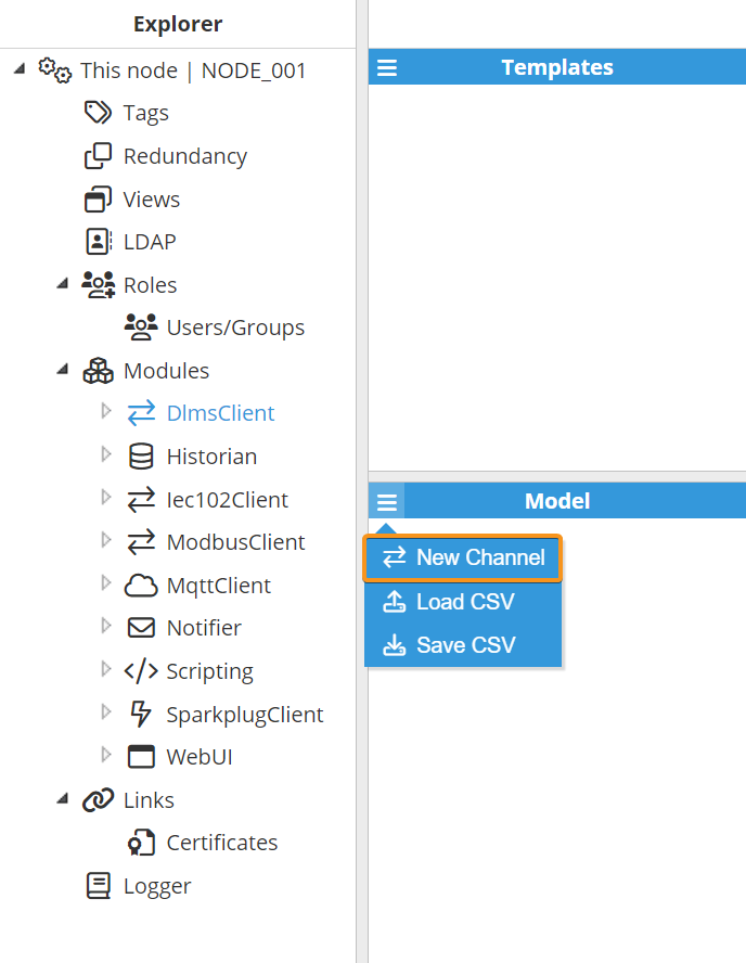
As shown in the previous screenshot, multiple connections can be created in the Model panel by clicking on the burger menu icon. Each connection is referred to as a Channel. For a comprehensive understanding of the diverse configuration options, please refer to the explanation provided below.
Channel Configuration.png)
A channel represents the physical medium that will be used for communication between N3uron and remote DLMS devices. Each channel has the following parameters:
Enable data collection: When Disabled, the connection will remain inactive and all associated tags will remain as Bad-Uninitialized. The default setting is Enabled.
Connection:
Type: Defines the connection type.
TCP: Establishes a connection to the device using an IP address and port. This option is recommended for devices with an Ethernet port or those employing an Ethernet-to-serial converter.
Serial: Establishes a connection over a physical serial port on the host machine.
Each TCP channel includes the following parameters:
Config:
Host: Hostname or IP address of the target device.
TCP port: TCP port of the target device within the valid range of 1 to 65535. The default value is 4059.
Reconnect delay: Time before attempting to reopen a failed connection, displayed in milliseconds. The default value is 60,000 ms, with a minimum of 1,000 ms.
A Serial channel includes the following parameters:
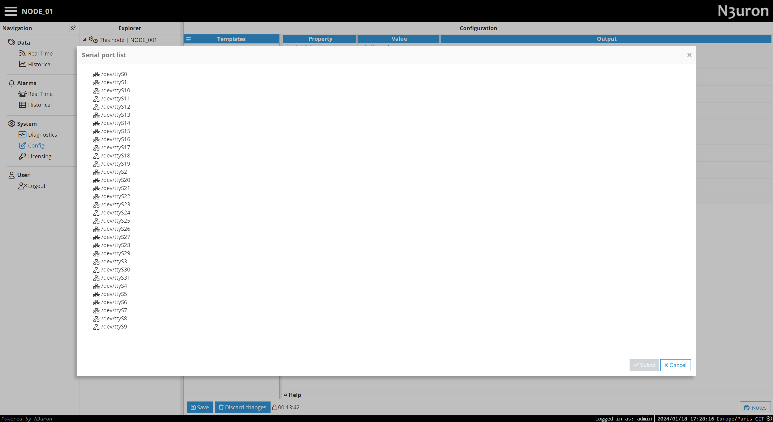
Port name: Serial port as displayed by the operating system (e.g., COM1, COM2 on Windows; /dev/ttyS0, /dev/ttyS1 on Linux).
Note:
The dropdown menu for serial port selection is available from N3uron version V1.21.7 onwards.
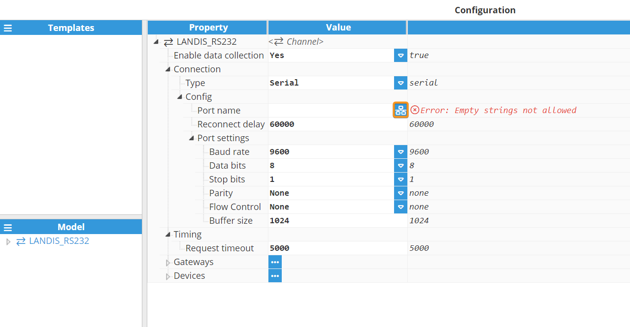
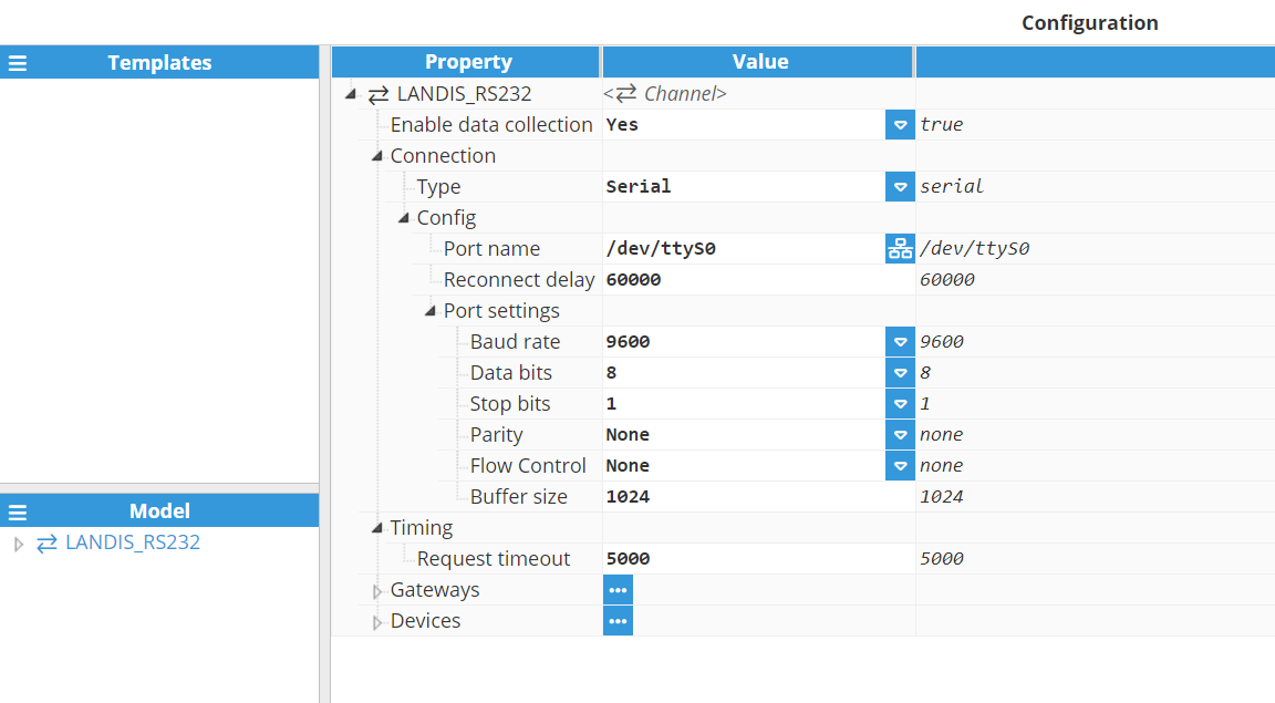
Reconnect delay: Time before trying to reopen a failed serial port, displayed in milliseconds. The default value is 60,000 ms, with a minimum of 1,000 ms.
Port settings:
Baud rate: Serial port transfer speed. Valid values include 110, 300, 1200, 2400, 4800, 9600, 19200, 38400, 57600 or 115200. The default value is 9600.
Data bits: Number of data bits per data word. Valid values are 5, 6, 7, or 8. The default value is 8.
Stop bits: Number of stop bits per data word. Valid values are 1 or 2. The default value is 1.
Parity: Data parity type. Valid options are none, even, mark, odd, or space.
Flow control: Enables the use of RTS/CTS (RS232) and RTS (RS485/RS422) control lines.
Buffer size: Serial communication buffer capacity. Valid range from 128 to 65536. The default value is 1024.
Timing:
Request timeout: Maximum amount of time to wait for a valid response, in milliseconds. The valid range is 100 to 600,000 ms.
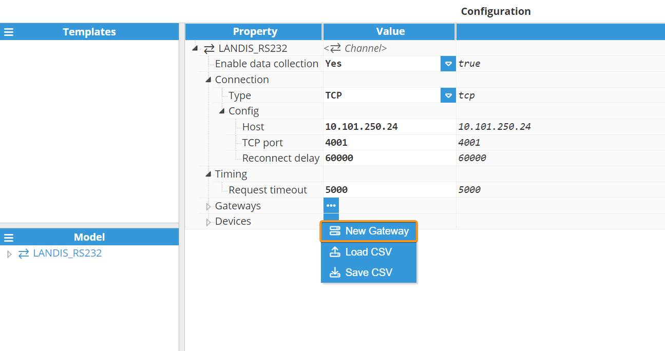
Gateways
In certain scenarios, a port used for connecting to a meter might need to be shared with other applications and clients. Concurrent access to the port can lead to collisions and communication errors. Introducing a gateway to a channel allows a third-party application to access the meter, mitigating these issues.
The gateway on a channel actively listens to a designated TCP port, awaiting incoming connections. When a third-party application connects, communication with all devices in the channel pauses, facilitating a transparent connection between the application and any device in that channel. Once the application disconnects from the gateway , the driver automatically resumes communication with the devices.
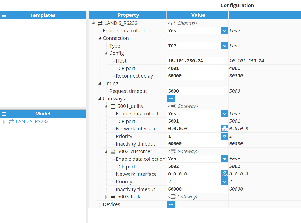
Configuration of a gateway includes the following parameters:
Enable data collection: Enables or disables the gateway.
TCP port: The gateway listens to this port for any incoming connections. The selected port must not be used by any other gateway or application on the same machine. The valid range is 0 to 65535 with a default value of 5001.
Network interface: Permitted interface for incoming connections.
0.0.0.0 allows connections from any network interface available within the machine.
127.0.0.1 or localhost only allows connections from local applications.
Use a specific IP address for a network card in the machine to only allow connections from this interface.
Priority: Indicates the priority of this gateway relative to others on the channel. The valid range is from 1 (highest priority) to 10 (lowest priority). Each gateway sharing the same channel must have a unique priority. The default value is 1.
Inactivity timeout: When an application is connected but remains inactive (no traffic), it will automatically be disconnected from the gateway after this time. This allows data collection to be resumed in order to continue to update any tags associated with the channel. This value is expressed in milliseconds. The default value is 60,000 ms. A value of 0 will disable this functionality, allowing applications to remain connected indefinitely even when inactive.
Device Configuration
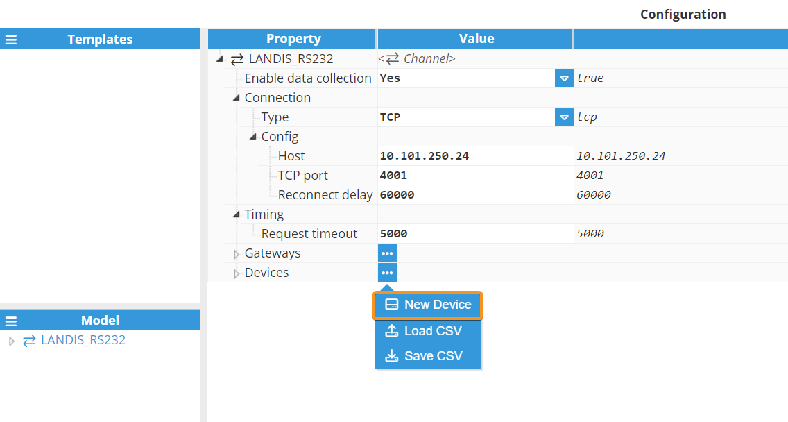
Once a Channel has been configured, a remote DLMS device can be added.
To create a new Device, you can click on the Devices button under Gateways and select New Device.
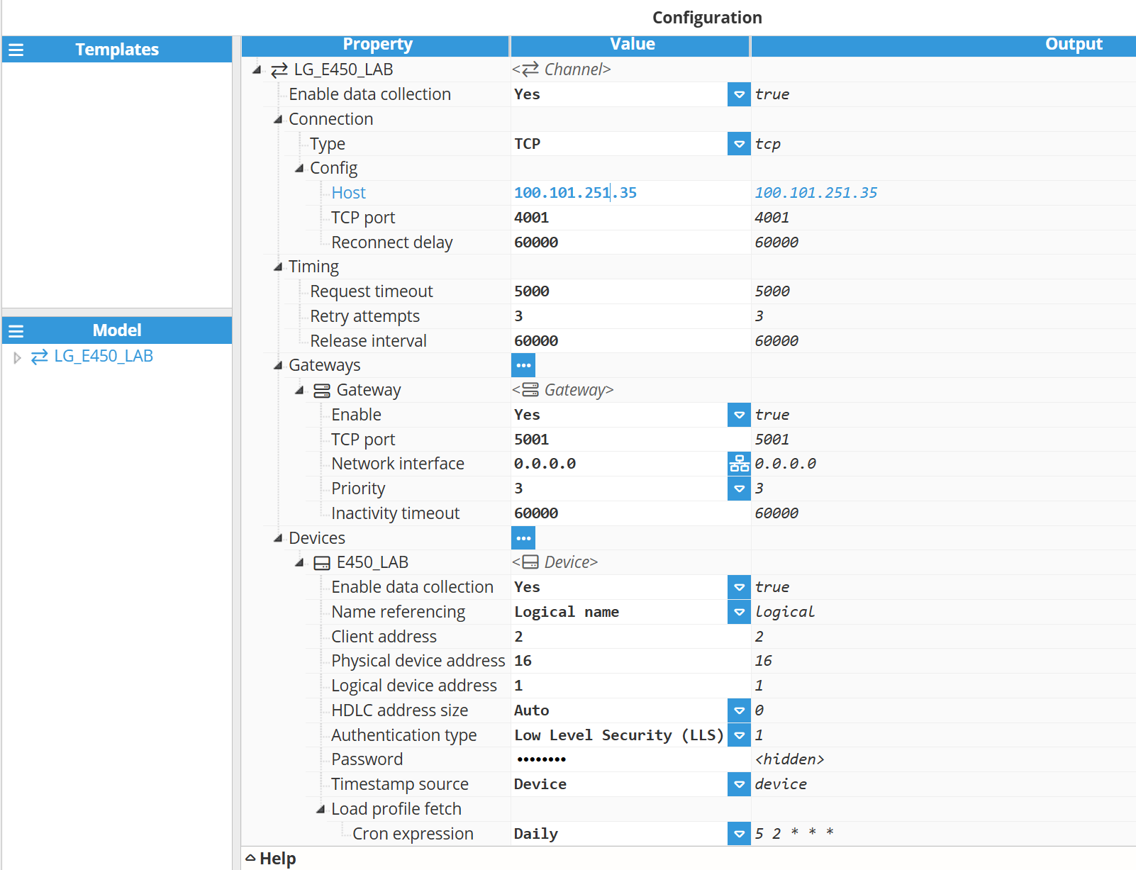
Once the device is created, configure the following parameters:
Enable data collection: Enable or disable data collection for this device. When disabled, no data will be sent to the device and associated tags will remain as Bad - Uninitialized.
Name referencing: Specifies the name referencing used by the meter to identify the objects.
Logical name: Objects and attributes are referenced using a string of 6 values defined in OBIS (Object Identification System).
Short name: Objects and attributes are uniquely identified by a 16-bit integer value.
Client address: Identifies the client when communicating with the meter and it is usually associated with the access level granted. The default value of the Client address for the public access level is 16 (in decimal), according to the DLMS standard. The Client address is an 8-bit number (from 0 to 255). Examples of default Client addresses and authentication used by manufacturers:
Cewe Prometer:
Client address: 24; password: ABCD0002 (Low-Level Security).
Client address: 32: password: ABCD0001 (Low-Level Security).
Iskraemeco:
Client address: 100 (no authentication).
Itron (former Actaris):
Client address: 16; (no authentication).
Client address: 1: password: ABCDEFGH (Low-Level Security).
Landis+Gyr:
Client address: 32; password: 00000000 (Low-Level Security).
Note:
These default values are provided as a reference, and actual values configured in the meter may vary.
Physical device address: The Physical device address identifies the device to connect to. This field is required especially when several devices share the same communication channel in order to identify each of them. Examples of default physical device addresses supported by manufacturers:
Cewe Prometer: 1.
Iskraemeco: 17.
Itron SL7000: 17.
Landis+Gyr power meter: 1. Alternatively the address may be the last 4 digits of the serial number + 1000. For example, for a serial number ending in 1234 the Physical address would be 2234.
Note:
These default values are provided as a reference, and actual values configured in the meter may vary.
Logical device address: The Logical device address identifies the logical device inside the physical device. Each physical device may contain several logical devices like the electrical meter, the communication unit, and the management device. The address for the management logical device is 1 and it is usually supported for all standard devices. Other logical device addresses must be obtained from the meter manufacturer.
HDLC address size: The size in bytes of the HDLC address sent to the device. The physical device address occupies the lower portion of the HDLC address, whereas the logical device address resides in the upper portion. Allowed values:
Auto: The size is calculated based on the value of the physical and logical device addresses.
1 byte: Sends only the logical device address in 1 byte while the physical device address is omitted. The option must be used only in point-to-point connections.
2 bytes: Sends logical and physical device addresses in 1 byte each one.
4 bytes: Sends logical and physical device addresses in 2 bytes each one.
Authentication type: Specifies an authentication mechanism used to establish an application association with the meter. Allowed values:
None: Authentication is not required. Allows the client to retrieve some basic information from the server.
Low Level Security (LLS): The server requires client authentication using a password that is known by the server.
Timestamp Source: Selects the source of the time along with the timezone and DST deviations used as timestamp for the events:
Device: Uses the time, timezone deviation and DST deviation provided by the device's clock. This driver considers positive deviations to the east of the UTC (UTC+) and negative deviations to the west of the UTC (UTC-). Choose custom deviations in case the device uses a different sign convention.
Device (custom timezone): Uses the time from the device and specific timezone and DST deviations provided by the user in the configuration. This option is recommended when the deviations by the device are different from expected, for instance, the device uses a different sign convention.
Local: Uses the time, timezone deviation and DST deviation provided by the clock of the local machine where N3uron is running.
Load profile fetch: Defines the schedule for the load profile retrieval (cron job) on this field device.
Cron expression: Cron jobs are executed based on the host machine's timezone. The cron expression consists of five fields, in the following order:
Minute (0 - 59).
Hour (0 - 23).
Day of the month (1 - 31).
Month (1 - 12).
Day of the week (0 - 7, where both 0 and 7 represent Sunday).
Predefined values:
Every 15 minutes (5,20,35,50 * * * *): Executes every 15 minutes at minutes 05, 20, 35, and 50 of each hour.
This 5-minute delay ensures that the complete data for the previous interval is available before the download is triggered. For example, if the task ran exactly at 00:00:00, the most recent data point might still be from 23:45:00. Delaying the request by 5 minutes allows time for any clock drift in the meter and guarantees that the latest data is reliably retrieved.Hourly (5 * * * *): Every hour at minute 05.
Daily (5 2 * * *): Every day at 02:05.
Weekly (5 2 * * MON): Every week on Monday at 02:05.
Monthly (5 2 1 * *): Every 1st day of the month at 02:05.
Other examples:
*/30 * * * *: At every 30th minute.
5 */12 * * *: At minute 5 every 12th hour.
5 9-17 * * *: At minute 5 past every hour from the 9th to the17th hour.
For more cron examples and additional information, visit Crontab Guru.
Note:
The Load profile fetch feature is available starting from N3uron version 1.21.13.
Tag Configuration via Drag and Drop
Tags can be added to the data model using the DLMS Client’s drag-and-drop feature. In the Browser section, users can select and drag tags or folders into the model. This action automatically applies the required connections and configurations, simplifying the setup process and ensuring consistent tag integration.
.gif)
Tag Configuration
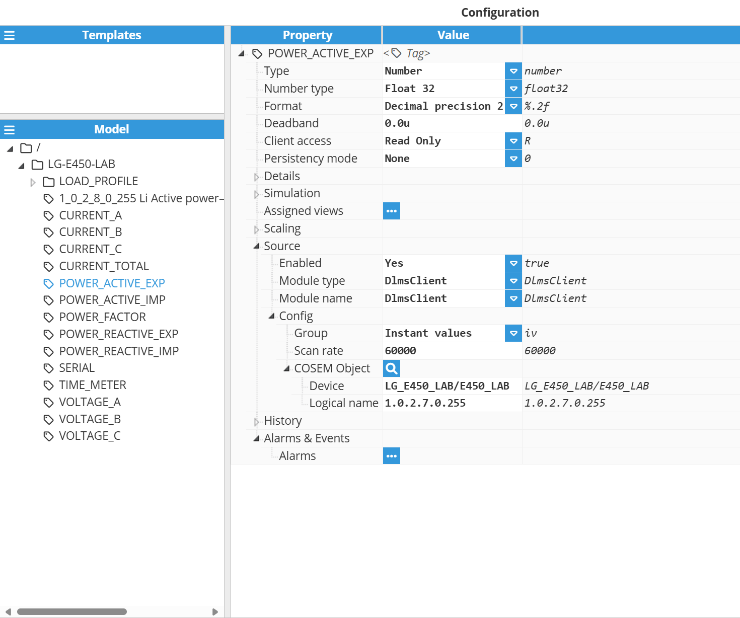
The channel and device configuration parameters define the settings for establishing connections to slave devices. Following the configuration of these elements, users will be able to create and configure all tags associated with the data received from DLMS devices, as shown in the example below:
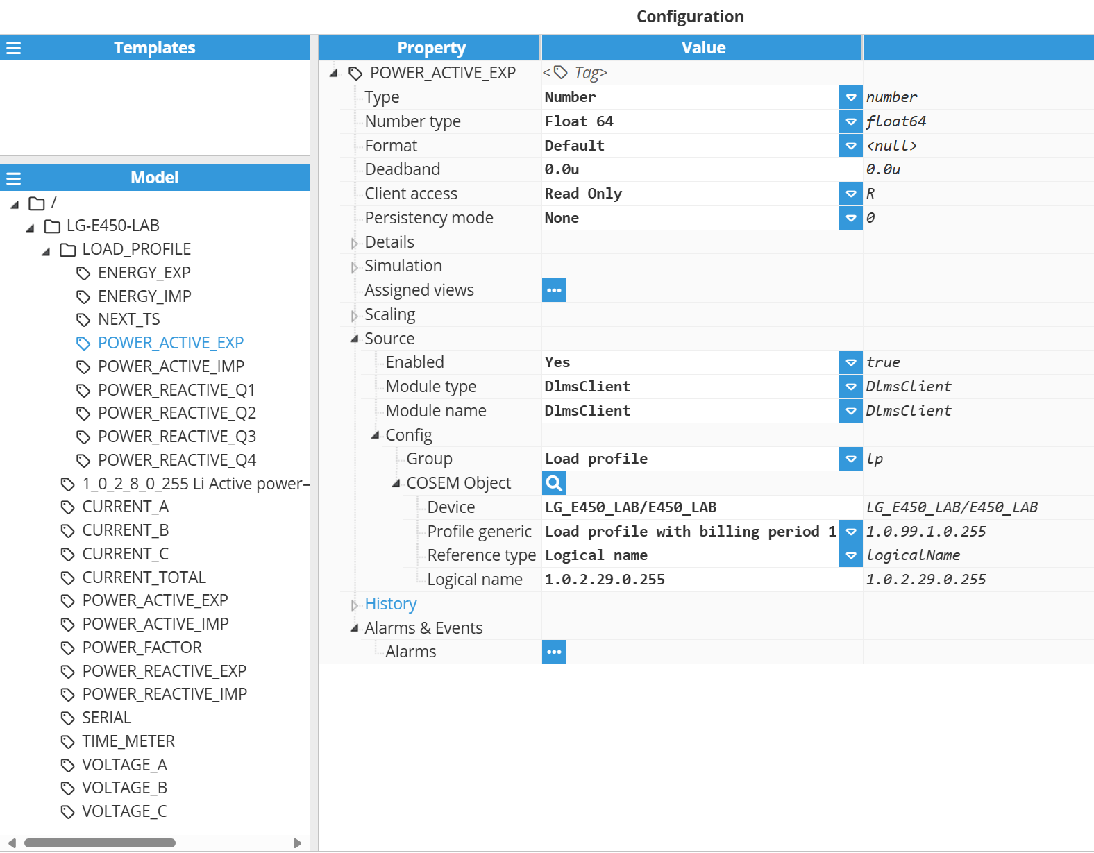
Source:
Enabled: When Disabled, tags won't be updated with the values received from the server, but instead, will essentially act as memory tags. When Enabled, the tag value will be continuously updated with the values received. The default value is set to Disabled.
Module type: The type of the module used to obtain the tag's value, quality and timestamp.
Module name: Name of the module used to obtain the tag's value, quality and timestamp.
Config:
Group: Specifies the type of data associated with the tag, based on how the information is retrieved from the meter.
Options:
Instant values: Real-time data read directly from the device, representing the current measurements at the time of the request.
Load profile: Historical data recorded in the meter over time. The driver starts collecting from the configured initial moment and, in case of a communication failure, resumes by retrieving all data stored since the last successful read.
Note:
Load profile feature is available from N3uron version 1.21.13.
Scan rate: Poll interval for this tag, in milliseconds. The default value is 5,000 ms. The minimum value is 1,000 ms.
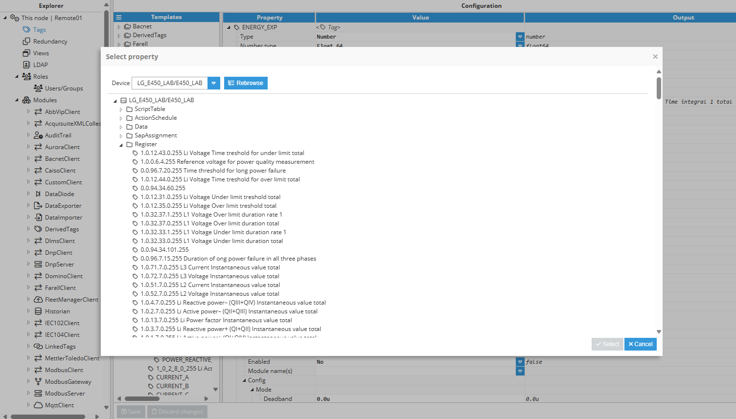
COSEM Object: Click the magnifying glass icon next to the COSEM Object label to open the COSEM Object Tag Browser. This utility lets you browse the available COSEM objects from the connected device. Once selected, it will automatically fill in the Device and Logical name fields to ensure accurate and error-free tag configuration.
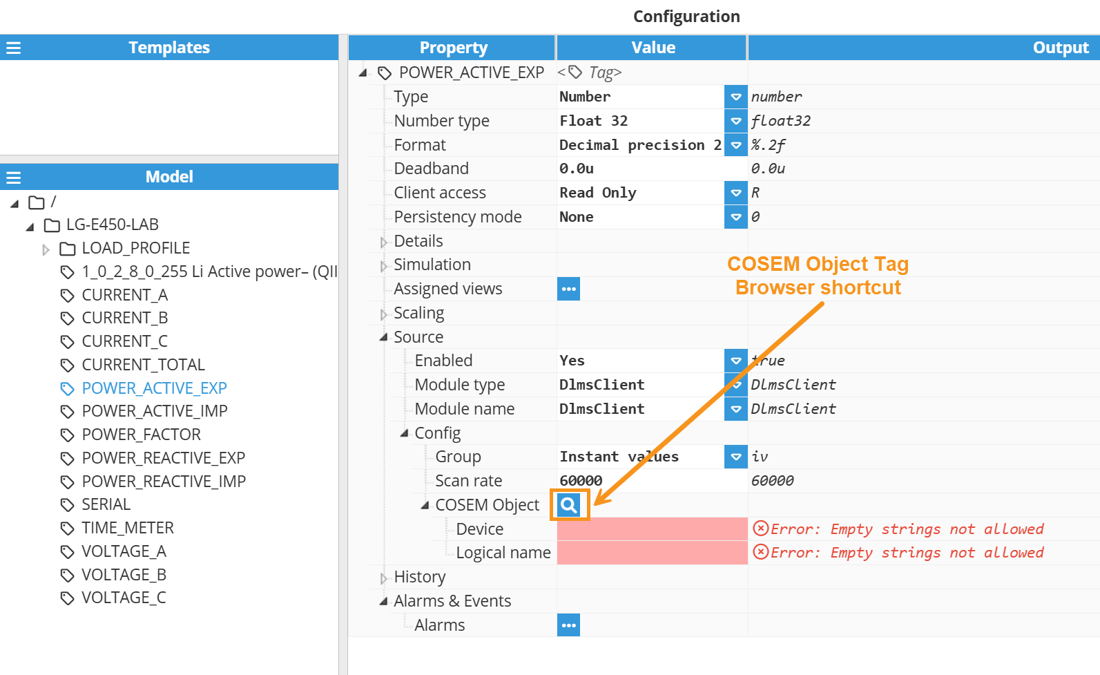
Device: Specifies the device providing data to this tag. The device must be created and configured in the DLMS client module connections.
Profile generic: This field becomes visible when the Load Profile group is selected. Specifies the OBIS code corresponding to the load profile (Profile Generic object) to be read from the meter. This parameter identifies the dataset where historical energy or power measurements are stored.
Options:
Load profile with billing period 1.
Load profile with billing period 2.
Reference type: This field becomes visible when the Load profile group is selected and specifies the method used to reference data from the selected load profile.
Options:
Logical name: Retrieves data using the OBIS codes (logical names) of the captured objects in the load profile.
Index: Retrieves data by index position within the received data array. Indexing starts at 0. Common index mappings are:
0: Profile record status.
1: Profile record timestamp.
2: Active energy imported.
3: Active energy exported.
4: Reactive energy Q1.
5: Reactive energy Q2.
6: Reactive energy Q3.
7: Reactive energy Q4.
Note:
Index Reference Type is useful when the meter does not provide definitions for the captured objects.
Important:
The default values provided in this example are for reference only. The meter's actual values may differ. For the correct values, please reach out to your meter provider.
Next request timestamp: Timestamp to be used as the starting point for the next load profile request. After a successful read, this value is automatically updated to the timestamp of the last record retrieved. Users can manually set this value to change the starting point for the next retrieval, enabling targeted access to specific historical data.
Logical name: Select the OBIS (Object Identification System) code to reference the COSEM object to read. OBIS codes follow the format A.B.C.D.E.F where:
Group A: Specifies the medium (0: Abstract objects, 1: Electricity, 7:Gas, etc.).
Group B: Specifies the channel.
Group C: Specifies the physical value (11: Current, 12: Voltage, 14: Frequency, etc.).
Group D: Specifies the type of aggregation applied to the physical quantity (7: Instantaneous value, 8: Time integral, 9: Time integral 2, etc.).
Group E: Specifies further processing or classification like tariff rates for energy (0: Total, 1: Rate 1, 2: Rate 2, etc.) or harmonics for instantaneous values (0: Total, 1: Fundamental, 2: 2nd harmonic, etc.).
Group F: Specifies historical values of data.
Examples:
1.0.1.7.0.255: Total Active Power - instantaneous value.
1.0.3.7.0.255: Total Reactive Power - instantaneous value.
1.0.9.7.0.255: Total Apparent Power - instantaneous value.
Refer to this link for more detailed information on creating tags.
DLMS Client Full Product Details