Note
Before starting configuration, a new module instance must be created.Click here for more information about creating Module instances.
Channel configuration
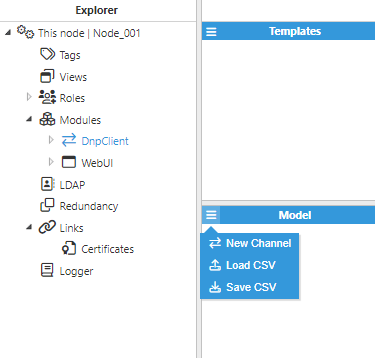
By selecting DnpClient in the Explorer tree menu, new channels can be created to connect to DNP3 slaves (aka outstations).
A channel represents the physical medium of connecting one or more devices. Each channel requires the following parameters:
Enable data collection: When disabled, the channel will remain inactive. The default value is set to Enabled.
Timing:
Request timeout: Maximum time spent waiting for a valid response, displayed in milliseconds. The valid range is 100ms to 600000ms. The default value is 3000ms.
Retry attempts: Number of communication retries before considering the target device unreachable. The valid range is 0 to 100. The default value is 3.
Inter-request delay: Delay before sending the next request to the target device, displayed in milliseconds. The valid range is 0ms to 600000ms. The default is 0ms.
Connection:
Type: Defines the connection type
TCP: Connects via a TCP socket.
Serial: Connects via a serial port.
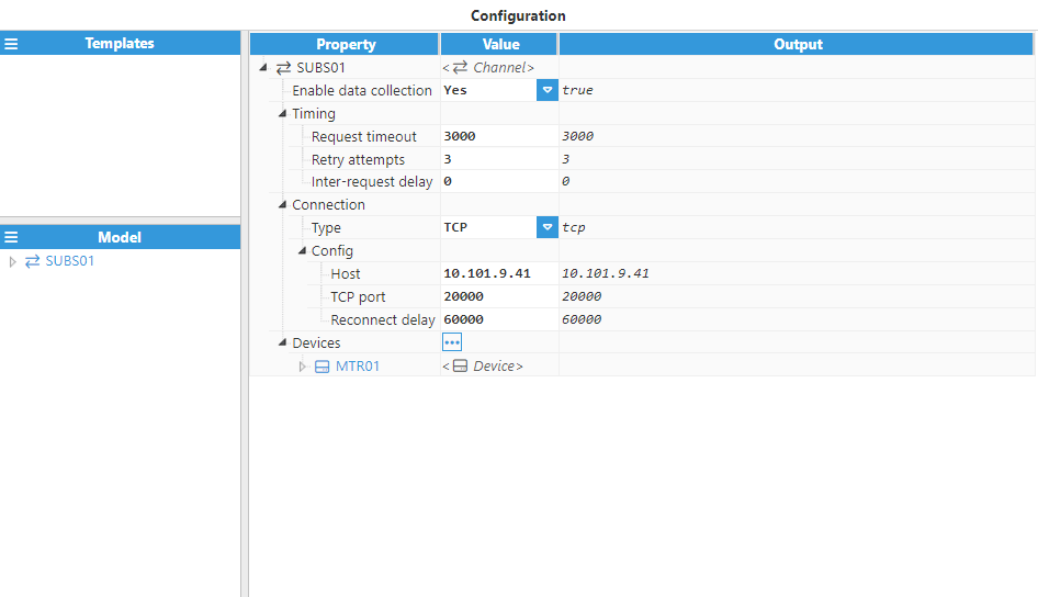
Configuring a TCP channel requires the following parameters:
Host: Hostname or IP address of the target device.
TCP port: TCP port of the target device. The valid range is 1 to 65535. The default value is 20000.
Reconnect delay: Time before attempting to re-open a failed connection, displayed in milliseconds. The minimum value is 1000ms.
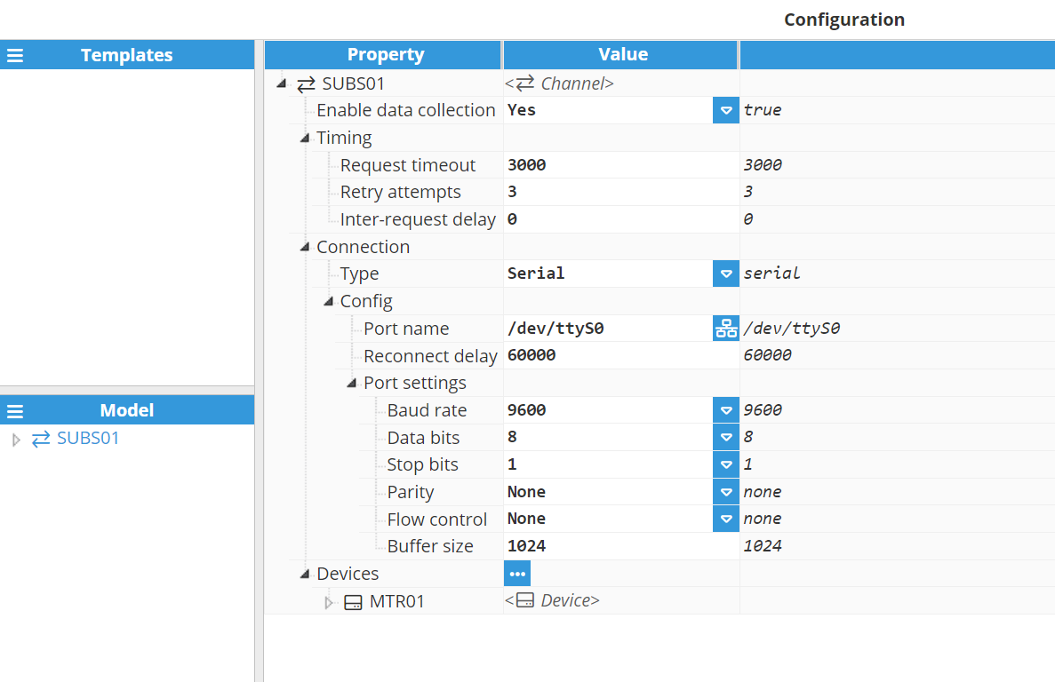
Configuring a serial channel requires the following parameters:
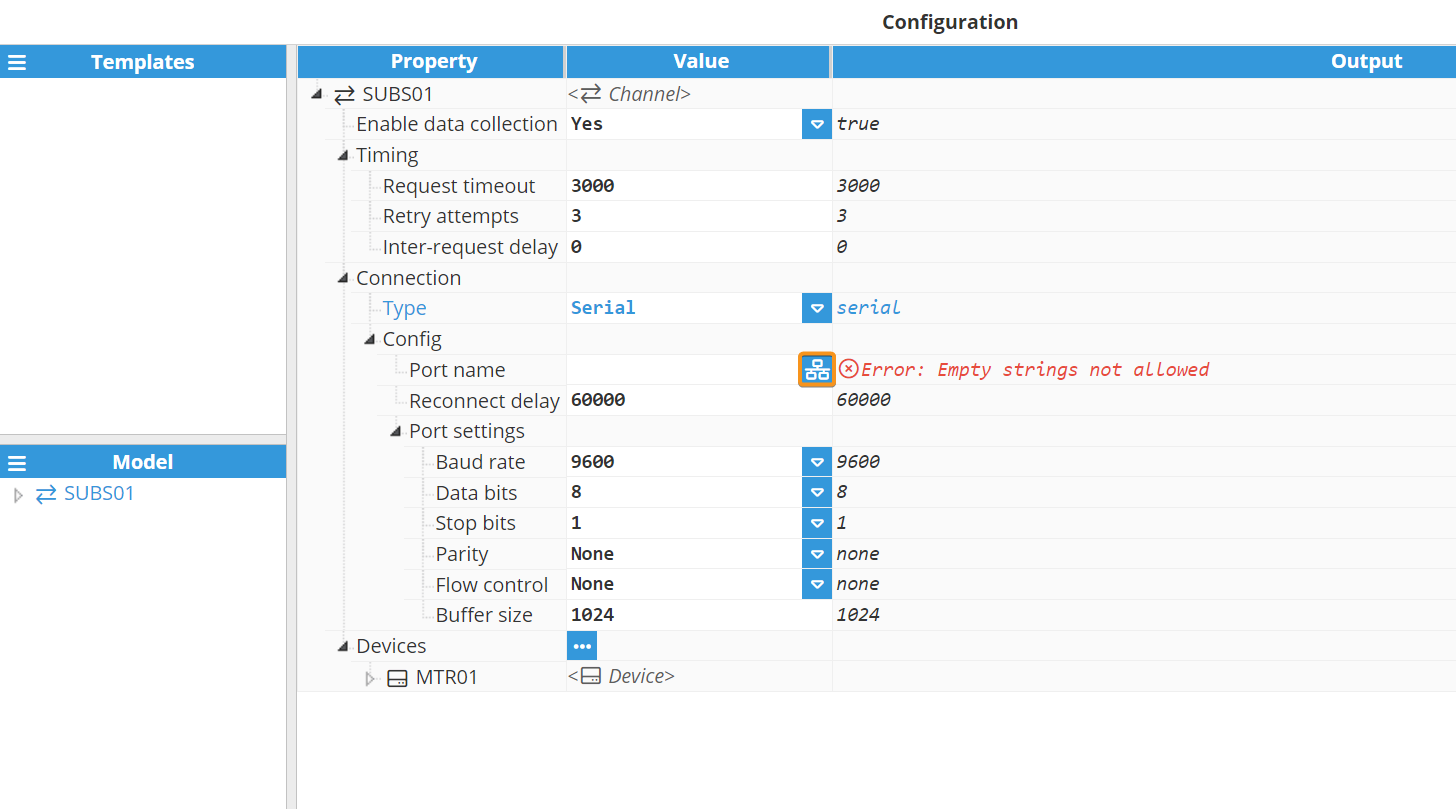
Port name: Serial port as displayed by the operating system. For example, if N3uron is running in Windows, valid port names would be COM1, COM2 and so forth, whilst if running on Linux, valid port names would be /dev/ttyS0, /dev/ttyS1, and so forth.
Note:
The dropdown menu for serial port selection is available from N3uron version V1.21.7 onwards.
.png)
Reconnect delay: Time before trying to re-open a failed serial port, in milliseconds. The minimum value is 1000ms.
Port settings:
Baud rate: Serial port transfer speed.
Data bits: Number of data bits per data word. Valid values are 5, 6, 7 or 8.
Stop bits: Number of stop bits per data word. Valid values are 1 or 2.
Parity: Data parity type. Valid options are none, even, mark, odd or space.
Flow control: Enables the use of RTS and DTR control lines.
Buffer size: Serial communication buffer capacity.
Device configuration
Each channel can connect to one or more devices. A typical example of a channel containing a single device would be a direct TCP or serial connection to a DNP3 slave. An example of multiple devices in the same channel would be when DNP3 slaves are connected within the same serial bus.
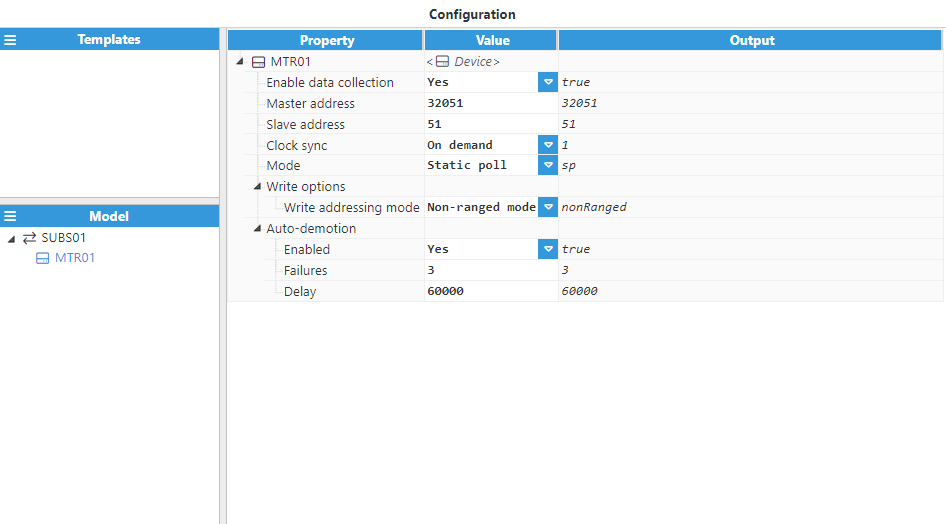
Device configuration settings contain the following fields:
Enable data collection: Enables or disables data collection on the specified device. When disabled, the channel will remain inactive. The default value is set to Enabled. If disabled, data will not be sent to the device and the quality status of tags will remain as “Bad – Uninitialized”.
Master address: In DNP3, each device must have a unique 16-bit address. This parameter specifies the DNP3 master address. The valid range is 0 to 65535. The default value is 0.
Slave address: Specifies the 16-bit address of the DNP3 slave or outstation. The valid range is 0 to 65535. The default value is 1.
Clock sync: Specifies how to synchronize the slave device with the master’s clock. Offers the following options:
Never: Master will not respect time synchronization requests from the device. The request will be acknowledged, but time will not be synchronized.
On demand (default): Master will only synchronize when requested by the slave.
Always: Master will synchronize every time communication is established.
Mode: Defines how the master retrieves data from the slave:
Static poll: Master will periodically request data according to the scan rate of each tag. Tags with the same scan rate will be organized into blocks of consecutive indexes in order to minimize the amount of polls/responses required.
Event poll: Master will periodically poll each event class for data changes using the scan rates configured for each event class. To check the integrity of the data, current values will be queried every time a connection is established at the rate specified for class-0.
Class-0 data: Collects the current value of all signals (also known as integrity check). This parameter specifies the scan rate of this integrity check in milliseconds.
Class-1 data: Specifies the poll interval for class-1 events, in milliseconds. Minimum value is 0 (poll disabled for this class). The Default setting is 5000ms.
Class-2 data: Specifies the poll interval for class-2 events, in milliseconds. Minimum value is 0 (poll disabled for this class). The Default setting is 10000ms.
Class-3 data: Specifies the poll interval for class-3 events, in milliseconds. Minimum value is 0 (poll disabled for this class). The Default setting is 20000ms.
Write options:
Write addressing mode: Selects the qualifier that will be used to send write commands depending on the method supported by the outstation.
Range - index mode: Uses the 0x00, 0x01, 0x02 qualifier when writing. These qualifiers specify a contiguous block of objects delimited by a start and stop indixes.
Non-ranged mode: Uses the 0x17, 0x27, 0x37 qualifier when writing. These qualifiers specify a number of non-contiguous objects each prepended by their index.
Auto-demotion: Defines whether a device should be temporarily placed as “off-scan” when the device is not responding. If set to “off-scan”, read requests will not be sent to the device and any data associated with these read requests will automatically be set as “bad quality”. By placing a non-responsive device offline for a specific time period, the driver can continue to optimize its communications with other devices in the same channel. Once this demotion period has been reached, the driver will re-attempt to communicate with the non-responsive device. If the device is responsive, it will be placed as “on-scan”; otherwise, the off-scan time period will be restarted.
Enabled: When set to enabled, the device will automatically be taken “off-scan” until it starts to respond again.
Failures: Specifies how many successive cycles of request timeouts and retries can occur before the device is placed “off-scan”. The minimum value is 1. The default value is 3.
Delay: Determines the demotion period and indicates how long the device should be placed “off-scan” when the failure value has been reached. When the specified period expires, the driver will place the device as “on-scan” and allow another communication attempt to be made. The minimum value is 1000. The default value is 60000 milliseconds.
Tag configuration
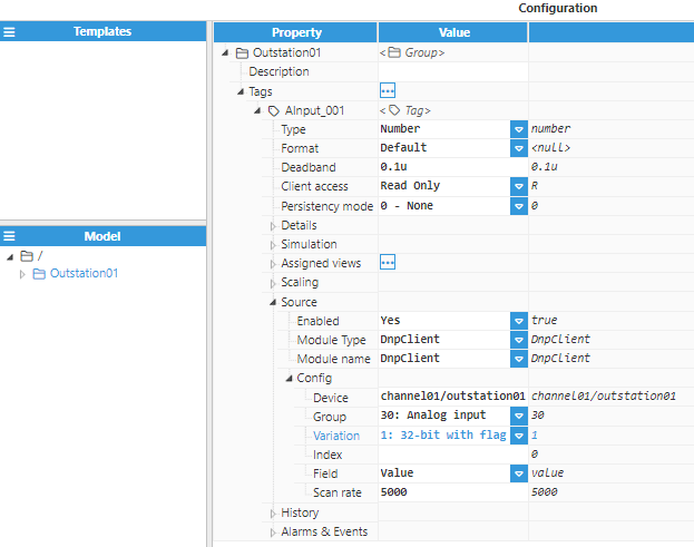
The channel and device configuration define the settings for establishing connections to the slave device. After configuring these elements, users will be able to create and configure any tags associated with the data received from DNP3 outstations, as seen in the following example:
Note:
This feature is available from N3uron version 1.21.8.
Implemented batch writing for direct operate no ack and non-ranged mode operations.
Source configuration settings contain the following parameters:
Enabled: When disabled, tags will not be updated with the values received from the device, but instead, will essentially act as memory tags. When set to enabled, the tag value will be continuously updated with the values received from the field device. The default value is set to Disabled.
Module type: Defines the driver type used to retrieve values from the field. In this example, DnpClient must be selected from the drop-down menu. If DnpClient does not appear in the drop-down menu, this means that this driver has not yet been installed on this machine and must be installed.
Module name: Defines the instance of the DNP Client created.
Config:
Device: This is the device that has already been created in previous steps to act as the data source. It should be referenced in the following format: channel/device.
Group: Defines the tag’s data object group according to the DNP3 specification. The following groups are supported:
01: Binary input
03: Double-bit input
10: Binary output
20: Counter
21: Frozen counter
30: Analog input
31: Frozen analog input
40: Analog output
50: Date and time
Variation: Defines the tag’s data type according to DNP3 specification. For zero variation, the data format will be provided by the DNP3 slave. Variation is only applicable to the Value field and therefore does not apply to Flag or Timestamp fields.
Index: Defines specific data objects in a given group. Indexes start with 0 for each object group containing multiple points. Essentially, this is the tag address.
Field: Certain object group variations in the DNP3 protocol will return multiple data items, such as Value, Flag and Timestamp.
Value: The value of the specified point
Flag: A byte containing the full set of transaction flags (0 through 7) for the specified DNP point.
0: Online
1: Restart
2: Communications Lost
3: Remote Force
4: Local Force
5: Overrange
6: Reference Check
7: Reserved
Command mode: DNP3 command to be used for write requests.
5: Direct operate. Send requests to a remote device requiring acknowledgment from the device..
6: Direct operate no-ack. Send requests to a remote device without requiring acknowledgment from the device.
Timestamp: The timestamp of the specified event.
Scan rate: Poll interval for the specified tag, in milliseconds. The minimum value is 100ms. Only applicable when the device mode is set to static polling.