Note:
Before starting configuration, a new module instance must be created. Click here for more information about creating Module instances.
Channel Configuration
New channels can be created by selecting the DNP3 Server instance from the Explorer tree menu.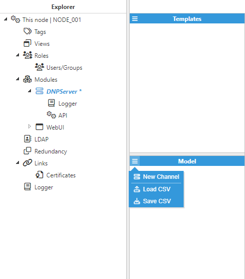
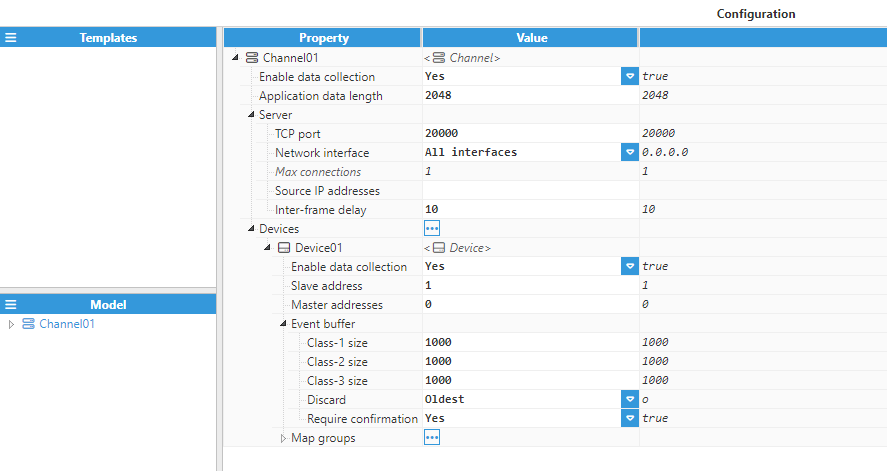
A channel represents the physical medium to which one or more slave devices can be linked. Each channel requires the following parameters to be configured:
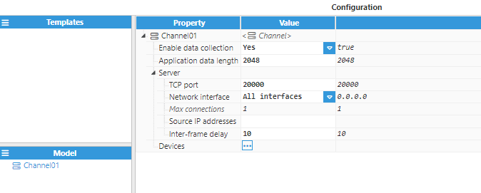
- Enable data collection: When disabled, the channel will remain inactive. The default value is set to Enabled.
- Application data length: The size of the application data buffer to be sent in a single transaction. The valid range is 1 to 65535. The default value is 2048.
- Server:
- TCP port: TCP port for incoming connections. The valid range is 1 to 65535 and the default port number is 20000. This port may not be used by any other application on the same machine.
- Network interface: Specifies the interface via which the DNP3 Server will be accessible. If set to All interfaces, the DNP3 Server will listen to connections on all interfaces. If set to Localhost only, the DNP3 Server will only listen to localhost connections. In addition to the above options, the IP address for a specific network interface can also be set to only allow connections from its own network.
- Max connections: The maximum number of TCP clients supported by this server. Only 1 permitted.
- Source IP addresses: Allows IP addresses to be whitelisted for incoming connections. Several IP addresses can be permitted using a comma-separated list. No restrictions are applied when left empty.
- Inter-frame delay: Time to wait between one frame and the next when sending multi-frame messages, displayed in milliseconds. The valid range is 0ms to 1,000ms, the default is 10ms.
Device Configuration
Each channel can have one or multiple devices.
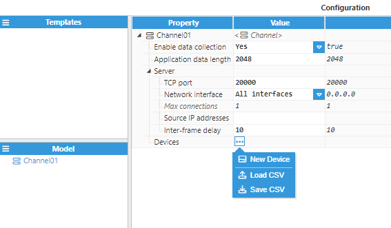
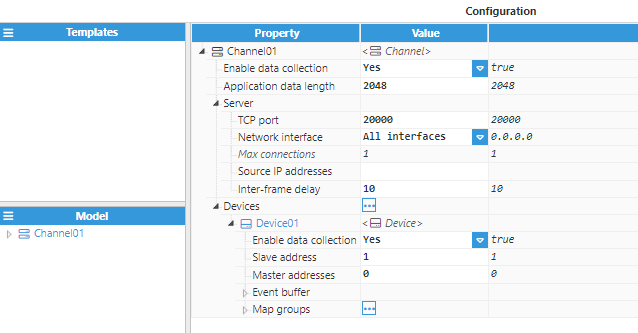
Device configuration settings contain the following options:
- Enable data collection: Enables or disables data collection on the specified device. When disabled, all requests will be discarded and no data will be sent back to the master.
- Slave address: Specifies the 16-bit address of the slave outstation. The valid range is 0 to 65535. The default value is 1.
- Master addresses: In DNP3, each device must have a unique 16-bit address. This parameter specifies the DNP3 master address. The 16-bit address of the master station(s) allowed to communicate with this device. The valid range is 0 to 65535. The default value is 0.
- Event buffer:
- Class-1 size: The size of the event buffer for Class-1 events. Set to 0 to disable. The default value is 1000.
- Class-2 size: The size of the event buffer for Class-2 events. Set to 0 to disable. The default value is 1000.
- Class-3 size: The size of the event buffer for Class-3 events. Set to 0 to disable. The default value is 1000.
- Discard: The type of events to discard when a buffer reaches its max size. If set to Oldest, the DNP3 Server will discard the oldest events. If set to Most Recent, the DNP3 Server will discard the most recent events.
- Require confirmation: Request the master to send a confirmation message after receiving and processing each set of events. The slave will wait for a valid confirmation in order to delete the set of events from the buffer.
- Map groups:
- Tag maps:
- Tag: Target tag to obtain updates from and send write requests to.
- DNP data point:
- Index: Specifies the DNP index. The valid range is 0 to 4294967295. The default value is 0.
- Event class: Available options are Class-0 (static), Class-1, Class-2, and Class-3.
- DNP data point:
- Tag: Target tag to obtain updates from and send write requests to.
- Tag maps:
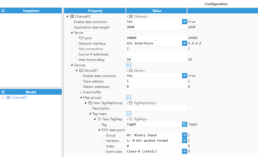
The available groups and variations are shown in the following table:
| Object Description | Object Type | Variations |
| Binary Inputs | 01 | 1: 8-bit-packed format 2: 8-bit with flag |
| Double-bit Inputs | 03 | 1: 8-bit-packed format 2: 8-bit with flag |
| Binary Outputs | 10 | 1: 8-bit-packed format 2: 8-bit with flag |
| Analog Inputs | 30 | 1: 32-bit with flag 2: 16-bit with flag 3: 32-bit without flag 4: 16-bit without flag 5: 32-bit floating-point with flag 6: 64-bit floating-point with flag |
| Analog Outputs | 40 | 1: 32-bit with flag 2: 16-bit with flag 3: 32-bit floating-point with flag 4: 64-bit floating-point with flag |