Exposing Power Meter data using DNP Server
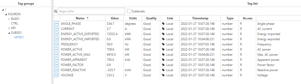
In this example, we are going to use DNP3 Server to expose data coming from a Power Meter that is being acquired through N3uron's Modbus Client.
Below is the memory map that will be configured in DNP3 Server:
| Power meter Communication protocol: DNP | |||||||
| Tag Name | DNP Group | DNP Variation | Index | Access | Units | Scaling | Description |
| ANGLE_PHASE | 30 | 5 | 0 | R | Degrees | 1 | Angle phase |
| CURRENT | 30 | 5 | 1 | R | A | 1 | AC current |
| ENERGY_ACTIVE_IMPORTED | 30 | 5 | 2 | R | kWh | 1 | Energy exported |
| ENERGY_ACTIVE_EXPORTED | 30 | 5 | 3 | R | kWh | 1 | Energy imported |
| FREQUENCY | 30 | 5 | 4 | R | Hz | 1 | Frequency |
| POWER_ACTIVE | 30 | 5 | 5 | R | kW | 1 | AC power |
| POWER_ACTIVE_MAX | 30 | 5 | 6 | R | kW | 1 | Max. AC power |
| POWER_APPARENT | 30 | 5 | 7 | R | kVA | 1 | Apparent power |
| POWER_FACTOR | 30 | 5 | 8 | R | 1 | Power factor | |
| POWER_REACTIVE | 30 | 5 | 9 | R | kVAr | 1 | Reactive power |
| VOLTAGE | 30 | 5 | 10 | R | V | 1 | Voltage |
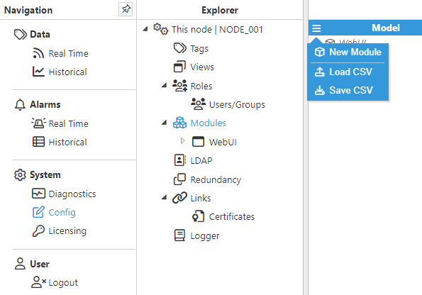
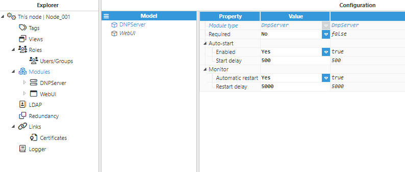
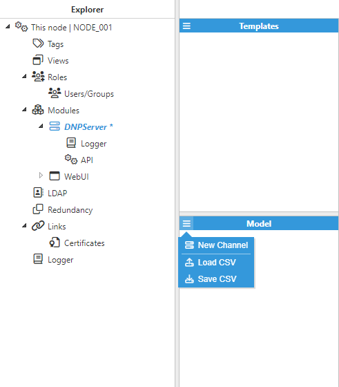
- Step 1: Add a new module in the "Modules" section, choose a name, and select "Dnp Server" in the "Module type" field.
- Step 2: Configure the Logger and API for the DNP3 Server module. In this example, the default configuration settings have been left unchanged, since in most cases, this is a valid configuration.
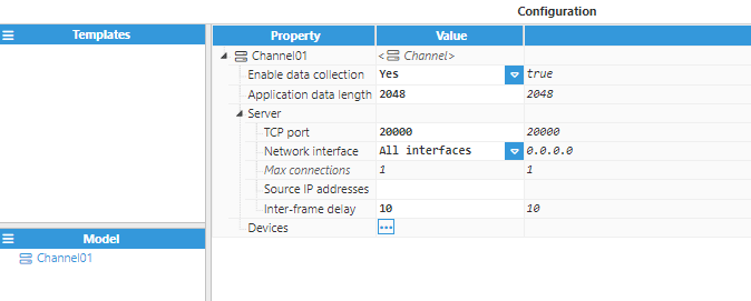
- Step 3: Add a new channel in the “Model” section and choose a name for it. The Source IP addresses field can be left empty in order to allow all IP addresses for incoming connections. However, specifying the Source IP address is strongly recommended, as this adds an extra layer of security.
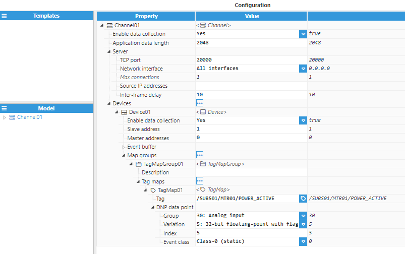
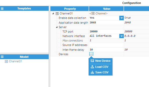
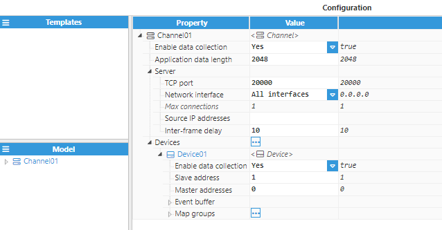
- Step 4: Add a new device in the “Configuration” section and configure the device.
- Step 5: Next, add a "Map group" and set its configuration.
- Step 6: Finally, add a "Tag Map" and start creating all tags from the Memory-Map (shown above). The following Figure shows the configuration settings for an Analog input tag. The rest of the tags should be configured in a similar way.