Each module has an API and Logger section that need to be configured separately. The default settings will be sufficient for this, but users will need to actively open the API and Logger configuration settings and save the default values to fully apply the settings.Click here for more information about API and Logger Configuration.
Channel Configuration
As shown in the screenshot below, multiple connections can be created in the Model Panel by clicking on the burger menu icon. Each connection is named Channel. See below for an explanation of the different configuration options.
.png) Figure 1. Module Configuration
Figure 1. Module Configuration
A channel represents the physical medium of connecting one or more devices. Each channel has the following parameters:
- Enabled: When disabled, the channel will remain inactive. The default value is set to Enabled.
- Centumb address: Specifies the address of the Centumb unit. The valid range is 0 to 15.
- Timing:
- Timeout: Maximum amount of time to wait for a valid response, displayed in milliseconds. The valid range is 100ms to 600,000ms. The default value is set to 10,000ms.
- Retry attempts: Number of communication retries before considering the target device unreachable. The valid range is 0 to 100. The default value is 3.
- Inter-request delay: Delay before sending subsequent requests to the target device, displayed in milliseconds. The valid range is 0ms to 600,000ms. The default is 0ms.
- Connection
- Type: Specifies the connection type that will be established.
- TCP
- Serial
- Type: Specifies the connection type that will be established.
When connecting via TCP, the following options are displayed:
- Config
- Host: Hostname or IP address of the target device.
- TCP port: Determines which TCP Port to connect to. Valid values range from 1 to 65535.
- Reconnect delay: Time before trying to re-open the connection after a failed attempt, displayed in milliseconds. The minimum value is 1,000ms.
The following image shows an example TCP connection configuration:
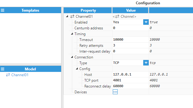 Figure 2. TCP Connection Configuration
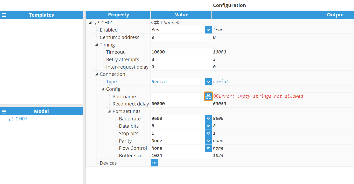
Serial channels include the following options:
- Config
- Port name: Serial port as displayed by the operating system. For example, if N3uron is running on Windows, valid port names would be COM1, COM2, and so forth. If running on Linux, valid port names would be /dev/ttyS0, /dev/ttyS1, and so forth.Note:The dropdown menu for serial port selection is available from N3uron version V1.21.7 onwards.
.png)
- Reconnect delay: Time before trying to re-open the serial port after a failed attempt, displayed in milliseconds. The minimum value is 1,000ms.
- Port settings:
- Baud rate: Serial port transfer speed in milliseconds. Valid values are 110, 300, 1200, 2400, 4800, 9600, 19200, 38400, 57600, or 115200.
- Data bits: Specifies the number of data bits per data word. Valid values are 5, 6, 7, or 8.
- Stop bits: Specifies the number of stop bits per data word. Valid values are 1 or 2.
- Parity: Specifies the type of data parity. Valid values are None, even, mark, odd, or space.
- Flow Control: Enables the use of RTS and DTR control lines. There are 3 options: None, RTS/CTS (RS232), and RTS (RS485/RS422).
- Buffer size: Specifies the Serial communication buffer capacity. The valid range is 128 to 65536.
- Port name: Serial port as displayed by the operating system. For example, if N3uron is running on Windows, valid port names would be COM1, COM2, and so forth. If running on Linux, valid port names would be /dev/ttyS0, /dev/ttyS1, and so forth.
The image below shows an example serial channel configuration:
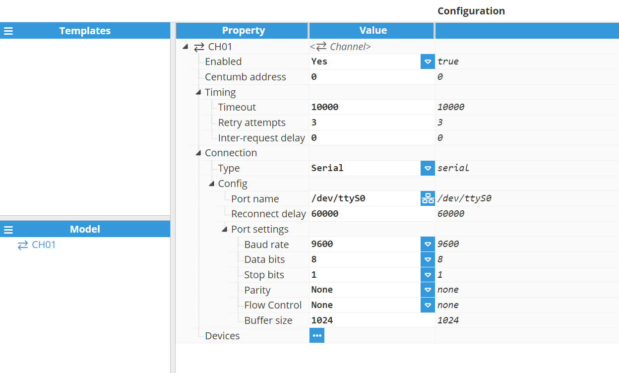 Figure 3. Serial Connection Configuration
Device Configuration
Each channel can have one or more devices. The Farell Client module offers the possibility of creating different devices belonging to Farell's UMB and TAF Series. The available devices are shown in the table below:
| Device |
| UMB-DS/DA |
| UMB-DS/DA vBA39 |
| UMB-DT |
| UMB-DT2 |
| UMB-SX |
| UMB-SD |
| UMB-BDr |
| UMB-BD/BD2 |
| TAF-5E/8E |
| TAF-16E/24E |
| TAF-8R |
Configuration will differ depending on which device is selected. Below you can find the configuration parameters for each of them.
- UmbDsDa
- Enabled: When disabled, the channel will remain inactive. The default value is set to Enabled.
- Device ID: Specifies the address of the remote device. The valid range is 1-255.
- Unsolicited Timeout: Maximum amount of time for receiving an unsolicited value update before the quality of the tag is changed to bad quality, displayed in milliseconds. The default value is 0, which means Unsolicited Timeout is deactivated.
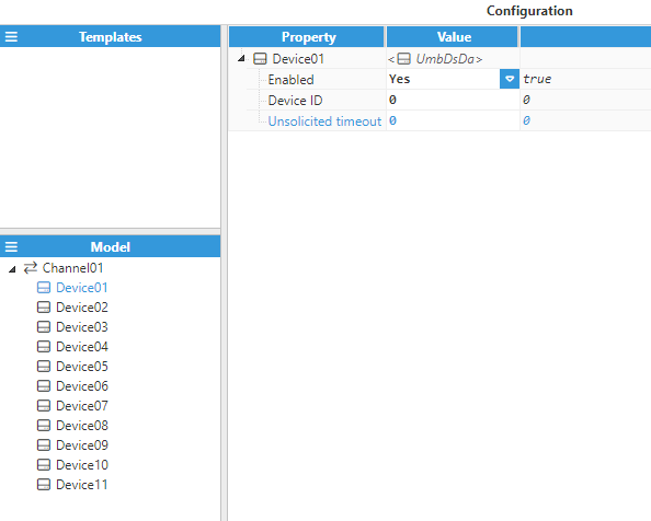 Figure 4. Device UmbDsDa configuration
- UmbDsDaBa39
- Enabled: When disabled, the channel will remain inactive. The default value is set to Enabled.
- Device ID: Specifies the address of the remote device. The valid range is 1-255.
- Unsolicited Timeout: Maximum amount of time for receiving an unsolicited value update before the quality of the tag is changed to bad quality, displayed in milliseconds. The default value is 0, which means Unsolicited Timeout is deactivated.
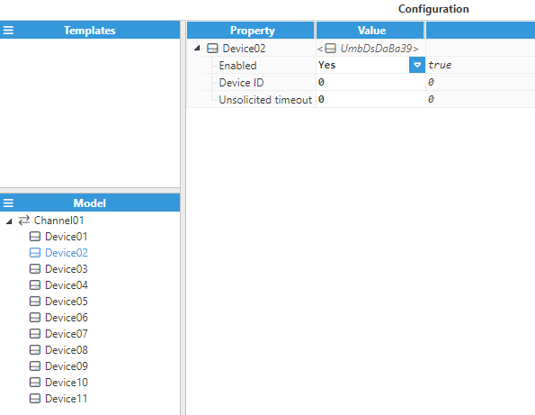 Figure 5. Device UmbDsDaBA39 configuration
- UmbDt
- Enabled: When disabled, the channel will remain inactive. The default value is set to Enabled.
- Device ID: Specifies the address of the remote device. The valid range is 1-255.
- Unsolicited Timeout: Maximum amount of time for receiving an unsolicited value update before the quality of the tag is changed to bad quality, displayed in milliseconds. The default value is 0, which means Unsolicited Timeout is deactivated.
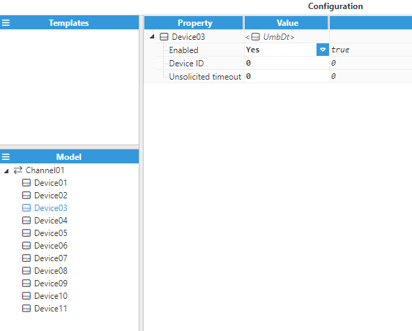 Figure 6. Device UmbDt configuration
- UmbDt2
- Enabled: When Disabled, the channel will remain inactive. The default value is set to Enabled.
- Device ID: Specifies the address of the remote device. The valid range is 1-255.
- Unsolicited Timeout: Maximum amount of time for receiving an unsolicited value update before the quality of the tag is changed to bad quality, displayed in milliseconds. The default value is 0, which means Unsolicited Timeout is deactivated.
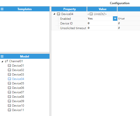 Figure 7. Device UmbDt2 configuration
- UmbSx
- Enabled: When disabled, the channel will remain inactive. The default value is set to Enabled.
- Device ID: Specifies the address of the remote device. The valid range is 1-255.
- Unsolicited Timeout: Maximum amount of time for receiving an unsolicited value update before the quality of the tag is changed to bad quality, displayed in milliseconds. The default value is 0, which means Unsolicited Timeout is deactivated.
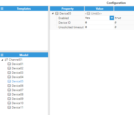 Figure 8. Device UmbSx configuration
- UmbSd
- Enabled: When Disabled, the channel will remain inactive. The default value is set to Enabled.
- Device ID: Specifies the address of the remote device. The valid range is 1-255.
- Unsolicited Timeout: Maximum amount of time for receiving an unsolicited value update before the quality of the tag is changed to bad quality, displayed in milliseconds. The default value is 0, which means Unsolicited Timeout is deactivated.
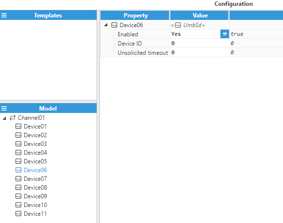 Figure 9. Device UmbSd configuration
- UmbBdr
- Enabled: When Disabled, the channel will remain inactive. The default value is set to Enabled.
- Device ID: Specifies the address of the remote device. The valid range is 1-255.
- Unsolicited Timeout: Maximum amount of time for receiving an unsolicited value update before the quality of the tag is changed to bad quality, displayed in milliseconds. The default value is 0, which means Unsolicited Timeout is deactivated.
- Auto-demotion: Defines whether data collection from a device should be paused after multiple successive failures in order to avoid affecting other devices on the same channel.
- Enabled: When set to Enabled, the device will be paused until the time specified in the Delay field has elapsed.
- Failures: Specifies the number of successive failures required before demoting the device. The minimum value is 1 and the default value is 3.
- Delay: Determines the time period before the device will be demoted once the maximum amount of failures has been reached and until a new communication attempt takes place. The minimum value is 1,000 and the default value is 60,000 milliseconds.
- Frame 94(Type 0)
- Enabled: Enables the reception of frames.
- Frame 94(Type 1)
- Enabled: Enables the reception of frames.
- Frame 94(Type 2)
- Enabled: Enables the reception of frames.
- Frame 94(Type 3)
- Enabled: Enables the reception of frames.
- Poll on demand:
- Enabled: Enables or disables the poll on demand mechanism.
- Tag: Tag that will be monitored to enable poll on demand for the device.
- Trigger on write: If enabled, poll on demand will be activated whenever a write command is sent to this device.
- Status tag: Optional. Tag showing the status of poll on demand on the device.
- Poll cycles: Number of scan clycles before poll on demand is turned off.
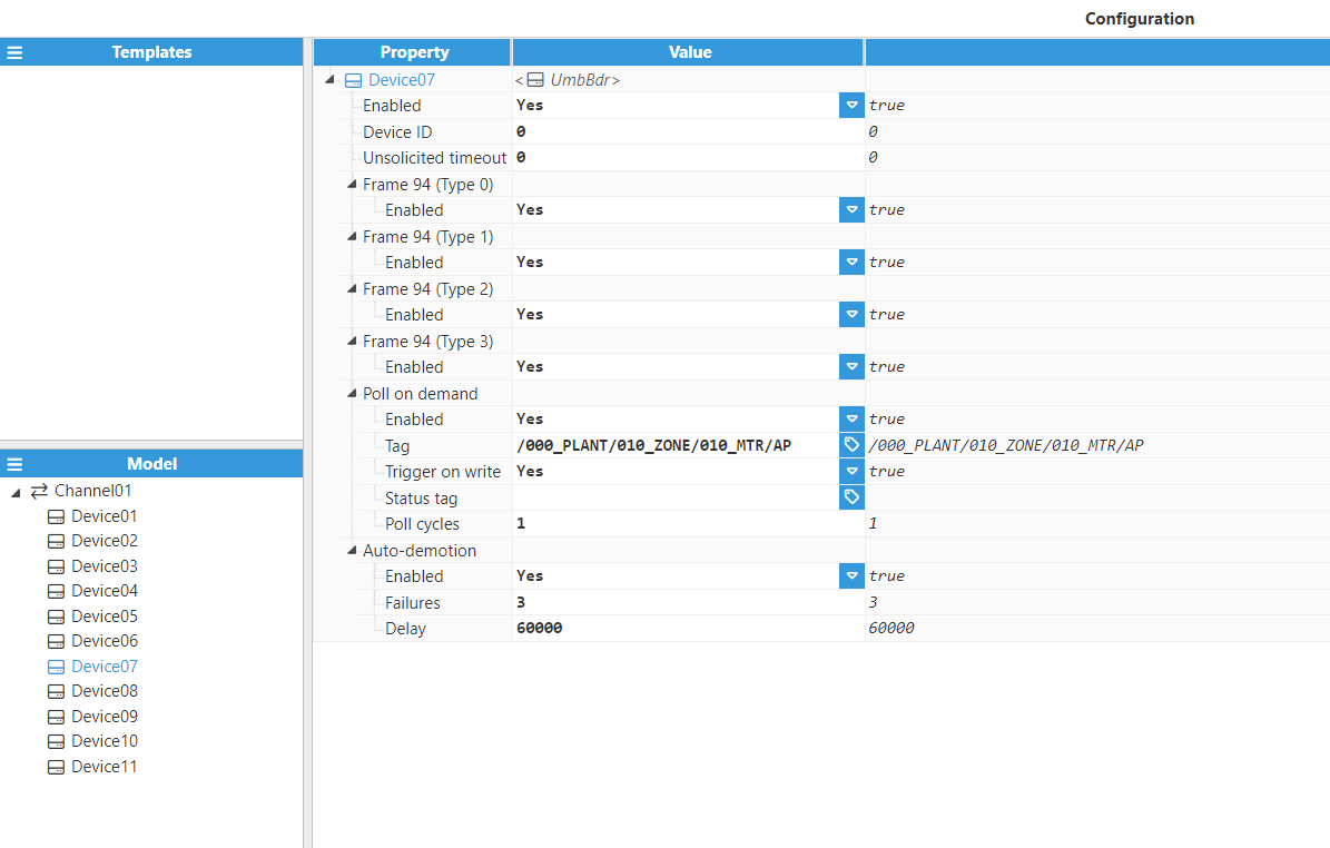 Figure 10. Device UmbBdr configuration
- UmbBdBd2
- Enabled: When disabled, the channel will remain inactive. The default value is set to Enabled.
- Device ID: Specifies the address of the remote device. The valid range is 1-255.
- Unsolicited Timeout: Maximum amount of time for receiving an unsolicited value update before the quality of the tag is changed to bad quality, displayed in milliseconds. The default value is 0, which means Unsolicited Timeout is deactivated.
- Auto-demotion: Defines whether data collection from a device should be paused after several successive failures in order to avoid affecting other devices on the same channel.
- Enabled: When set to enabled, the device will be paused until the time specified in the Delay field has elapsed.
- Failures: Specifies the number of successive failures required for demoting the device. The minimum value is 1 and the default value is 3.
- Delay: Determines the time period before the device will be demoted once the maximum amount of failures has been reached and until a new communication attempt takes place. The minimum value is 1,000 and the default value is 60,000 milliseconds.
- Frame 94(Type 0)
- Enabled: Enables the reception of frames.
- Frame 94(Type 1)
- Enabled: Enables the reception of frames.
- Frame 94(Type 2)
- Enabled: Enables the reception of frames.
- Frame 94(Type 3)
- Enabled: Enables the reception of frames.
- Poll on demand:
- Enabled: Enables or disables the poll on demand mechanism.
- Tag: Tag that will be monitored to enable poll on demand for the device.
- Trigger on write: If enabled, poll on demand will be activated whenever a write command is sent to this device.
- Status tag: Optional. Tag showing the status of poll on demand on the device.
- Poll cycles: Number of scan clycles before poll on demand is turned off.
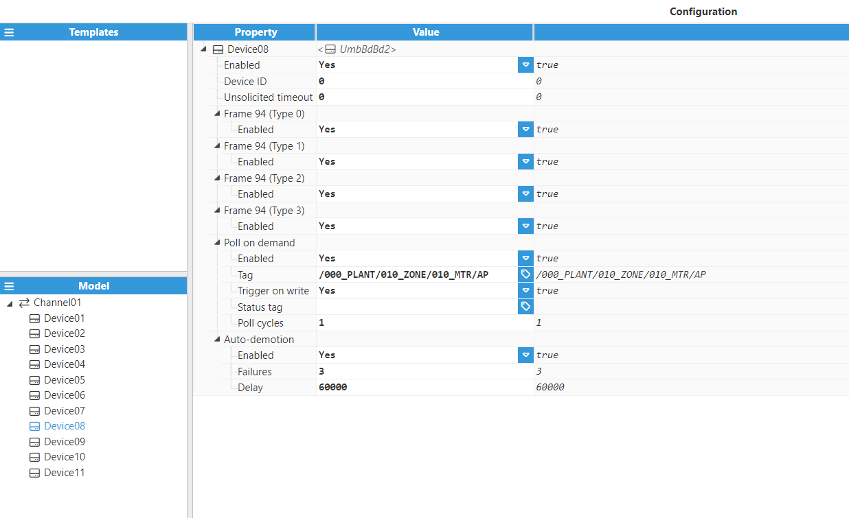 Figure 11. Device UmbBdBd2 configuration
- Taf5E8E
- Enabled: When Disabled, the channel will remain inactive. The default value is set to Enabled.
- Device ID: Specifies the address of the remote device. The valid range is 1-255.
- Unsolicited Timeout: Maximum amount of time for receiving an unsolicited value update before the quality of the tag is changed to bad quality, displayed in milliseconds. The default value is 0, which means Unsolicited Timeout is deactivated.
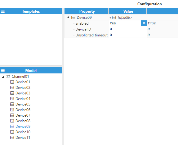 Figure 12. Device Taf5E8E configuration
- Taf16E24E
- Enabled: When Disabled, the channel will remain inactive. The default value is set to Enabled.
- Device ID: Specifies the address of the remote device. The valid range is 1-255.
- Unsolicited Timeout: Maximum amount of time for receiving an unsolicited value update before the quality of the tag is changed to bad quality, displayed in milliseconds. The default value is 0, which means Unsolicited Timeout is deactivated.
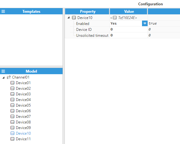 Figure 13. Device Taf16E24E configuration
- Taf8R
- Enabled: When Disabled, the channel will remain inactive. The default value is set to Enabled.
- Device ID: Specifies the address of the remote device. The valid range is 1-255.
- Frame 8R(Write Only)
- Retry attempts: Number of communication retries before considering the target device as unreachable. The valid range is 0 to 100. The default value is 3.
- Installer ID: Specifies the installer ID configured in the remote devices by Farell. This parameter is used to differentiate different networks working in the same area. This parameter is specific for UMB-TAF8R devices and is provided by Farell. The valid range is 0-255.
- Inter-Writes delay: Specifies the time between write retries, in milliseconds.
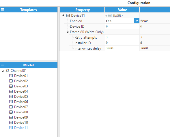 Figure 14. Device Taf8R configuration
Tag Configuration
Channel and device configuration parameters define the settings used for establishing connections to devices. After configuring these elements, users will be able to create and configure all tags associated with the data received from Farell devices, as seen in the below example.
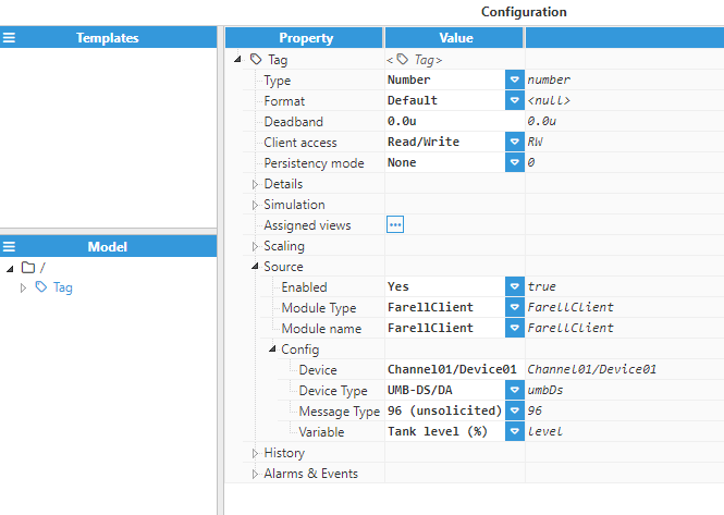 Figure 15. Tag Configuration
The only mandatory settings that need configuring are those contained within the source section. These parameters are listed below.
- Source
- Enabled: When Disabled, tags will not be updated with the values received from the device, but instead, will essentially act as memory tags. When set to Enabled, the tag value will be continuously updated with the values received from the field device. The default value is set to Disabled.
- Module type: Defines the driver type used to retrieve values from the field. In this example, FarellClient must be selected from the drop-down menu. If FarellClient does not appear in the drop-down menu, it means that this driver has not yet been installed on this machine and therefore, must be installed.
- Module name: Introduce the name of the Farell Client module instance that we previously created.
- Config:
- Device: Specify the previously created device that will act as the data source. The format must be Channel/Device. In this case, Channel01/Device01.
- Device type: Specify the type of the target device. In this case, UMB-DS/DA.
- Message Type: Specify the Frame ID where the value is received. In this case, 96 (unsolicited).
- Variable: Specify the signal of the remote device linked to the tag. In this case, Tank Level (%).
The message type depends on the device selected, just as the variables also depend on the message selected from the device. The following table shows the different types of messages and variables available for each device.
UMB-DS/DA | |
Message type | Variable |
Frame 96 | Digital Input 3 |
| Digital Input 4 | |
| Digital Input 5 | |
| Digital Input 6 | |
| Digital Input 7 | |
| Low Battery Warning | |
| Max. Level Alarm(negated) | |
| Min. Level Alarm | |
| Tank Level(%) | |
UMB-DS/DA vBA39 | |
Message type | Variable |
Frame 90 | Digital Input 3 |
| Digital Input 4 | |
| Digital Input 5 | |
| Digital Input 6 | |
| Digital Input 7 | |
| Digital Input 8 | |
| Empty Tank Alarm | |
| Low Battery Warning | |
| Max. Level Warning (negated) | |
| Tank Level (%) | |
UMB-DT | |
Message Type | Variable |
Frame 93 | Analog Input |
| Analog Input (Raw Dec. Position) | |
| Analog Input (Raw Integer) | |
| Digital Input 8 | |
| Digital Input 9 | |
| Digital Input 10 | |
| Digital Input 11 | |
| Digital Input 12 | |
| Digital Input 13 | |
| Digital Input 14 | |
| Digital Input 15 | |
| Digital Input 16 | |
| Low Battery Warning | |
| Trespassing Counter | |
| Water Meter 1 Flow (m3/h) | |
| Water Meter 1 Flow (Raw Dec. Position) | |
| Water Meter 1 Flow (Raw Integer) | |
| Water Meter 1 Volume (m3) | |
| Water Meter 2 Flow (m3/h) | |
| Water Meter 2 Flow (Raw Dec. Position) | |
| Water Meter 2 Flow (Raw Integer) | |
| Water Meter 2 Volume (m3) | |
| Water Meter 3 Flow (m3/h) | |
| Water Meter 3 Flow (Raw Dec. Position) | |
| Water Meter 3 Flow (Raw Integer) | |
| Water Meter 3 Volume (m3) | |
| Water Meter 4 Flow (m3/h) | |
| Water Meter 4 Flow (Raw Dec. Position) | |
| Water Meter 4 Flow (Raw Integer) | |
| Water Meter 4 Volume (m3) | |
Frame 96 | Digital Input 3 |
| Digital Input 4 | |
| Digital Input 5 | |
| Digital Input 6 | |
| Digital Input 7 | |
| Low Battery Warning | |
| Max. Level Alarm(negated) | |
| Min. Level Alarm | |
| Tank Level(%) | |
UMB-DT2 | |
Message Type | Variable |
Frame 92 | Analog Input 1 |
| Analog Input 1 ( Raw Dec. Position) | |
| Analog Input 1 (Raw Integer) | |
| Analog Input 2 | |
| Analog Input 2 ( Raw Dec. Position) | |
| Analog Input 2 ( Raw Integer) | |
| Digital Input 1 | |
| Digital Input 2 | |
| Digital Input 3 | |
| Digital Input 4 | |
| Digital Input 5 | |
| Digital Input 6 | |
| Digital Input 7 | |
| Digital Input 8 | |
| Digital Input 9 | |
| Digital Input 10 | |
| Digital Input 11 | |
| Digital Input 12 | |
| Digital Input 13 | |
| Digital Input 14 | |
| Digital Input 15 | |
| Digital Input 16 | |
| Low Battery Warning | |
| Trespassing Counter | |
| Water Meter 1 Flow (m3/h) | |
| Water Meter 1 Flow ( Raw Dec. Position) | |
| Water Meter 1 Flow (Raw Integer) | |
| Water Meter 1 Volume (m3) | |
| Water Meter 2 Flow (m3/h) | |
| Water Meter 2 Flow (Raw Dec. Position) | |
| Water Meter 2 Flow (Raw Integer) | |
| Water Meter 2 Volume (m3) | |
| Water Meter 3 Flow (m3/h) | |
| Water Meter 3 Flow (Raw Dec. Position) | |
| Water Meter 3 Flow (Raw Integer) | |
| Water Meter 3 Volume (m3) | |
| Water Meter 4 Flow (m3/h) | |
| Water Meter 4 Flow (Raw Dec. Position) | |
| Water Meter 4 Flow (Raw Integer) | |
| Water Meter 4 Volume (m3) | |
Frame 96 | Digital Input 3 |
| Digital Input 4 | |
| Digital Input 5 | |
| Digital Input 6 | |
| Digital Input 7 | |
| Low Battery Warning | |
| Max. Level Alarm(negated) | |
| Min. Level Alarm | |
| Tank Level(%) | |
UMB-SX | |
Message Type | Variable |
Frame 92 | Analog Input 1 |
| Analog Input 1( Raw Dec. Position) | |
| Analog Input 1 (Raw Integer) | |
| Analog Input 2 | |
| Analog Input 2 ( Raw Dec. Position) | |
| Analog Input 2 ( Raw Integer) | |
| Digital Input 1 | |
| Digital Input 1 | |
| Digital Input 1 | |
| Digital Input 1 | |
| Digital Input 1 | |
| Digital Input 1 | |
| Digital Input 1 | |
| Digital Input 1 | |
| Digital Input 1 | |
| Digital Input 10 | |
| Digital Input 11 | |
| Digital Input 12 | |
| Digital Input 13 | |
| Digital Input 14 | |
| Digital Input 15 | |
| Digital Input 16 | |
| Low Battery Warning | |
| Trespassing Counter | |
| Water Meter 1 Flow (m3/h) | |
| Water Meter 1 Flow (Raw Dec. Position) | |
| Water Meter 1 Flow (Raw Integer) | |
| Water Meter 1 Volume (m3) | |
| Water Meter 2 Flow (m3/h) | |
| Water Meter 2 Flow (Raw Dec. Position) | |
| Water Meter 2 Flow (Raw Integer) | |
| Water Meter 2 Volume (m3) | |
| Water Meter 3 Flow (m3/h) | |
| Water Meter 3 Flow (Raw Dec. Position) | |
| Water Meter 3 Flow (Raw Integer) | |
| Water Meter 3 Volume (m3) | |
| Water Meter 4 Flow (m3/h) | |
| Water Meter 4 Flow (Raw Dec. Position) | |
| Water Meter 4 Flow (Raw Integer) | |
| Water Meter 4 Volume (m3) | |
UMB-SD | |
Message Type | Variable |
Frame 91 | Analog Input |
| Analog Input (Raw Dec. Position) | |
| Analog Input (Raw Integer) | |
| Digital Input 8 | |
| Digital Input 9 | |
| Digital Input 10 | |
| Digital Input 11 | |
| Digital Input 12 | |
| Digital Input 13 | |
| Digital Input 14 | |
| Digital Input 15 | |
| Digital Input 16 | |
| Flat Period Energy (kWh) | |
| Instant Active Power (kW) | |
| Instant Active Power (Raw Dec. Position) | |
| Instant Active Power (Raw Integer) | |
| Low Battery Warning | |
| Off-Peak Period Energy (kWh) | |
| Peak Period Energy (kWh) | |
| Pump 1 On Operations | |
| Pump 1 Operating Time (h) | |
| Pump 2 On Operations | |
| Pump 2 Operating Time (h) | |
| Pump 3 On Operations | |
| Pump 3 Operating Time (h) | |
| Trespassing Counter | |
| Water Meter Flow (m3/h) | |
| Water Meter Flow (Raw Dec. Position) | |
| Water Meter Flow (Raw Integer) | |
| Water Meter Volume (m3) | |
UMB-BDr | |
Message Type | Variable |
Frame 94 (Type 0) | Analog Input 2 |
| Analog Input 2 (Raw Dec. Position) | |
| Analog Input 2 (Raw Integer) | |
| Analog Input 3 | |
| Analog Input 3 (Raw Dec. Position) | |
| Analog Input 3 (Raw Integer) | |
| Analog Input 4 | |
| Analog Input 4 (Raw Dec. Position) | |
| Analog Input 4 (Raw Integer) | |
| Analog Input 5 | |
| Analog Input 5 (Raw Dec. Position) | |
| Analog Input 5 (Raw Integer) | |
| Analog Input 6 | |
| Analog Input 6 (Raw Dec. Position) | |
| Analog Input 6 (Raw Integer) | |
| Analog Input 7 | |
| Analog Input 7 (Raw Dec. Position) | |
| Analog Input 7 (Raw Integer) | |
| Analog Output 1 | |
| Analog Output 2 | |
| Battery Voltage (Raw Dec. Position) | |
| Battery Voltage (Raw Integer) | |
| Battery Voltage (V) | |
| Current Tariff | |
| Digital Input 3 | |
| Digital Input 9 | |
| Digital Input 10 | |
| Digital Input 11 | |
| Digital Input 12 | |
| Digital Output 0 | |
| Digital Output 1 | |
| Digital Output 2 | |
| Digital Output 3 | |
| Digital Output 4 | |
| Digital Output 5 | |
| Digital Output 6 | |
| Digital Output 7 | |
| Digital Output 8 | |
| Digital Output 9 | |
| Digital Output 10 | |
| Digital Output 11 | |
| Digital Output 12 | |
| Digital Output 13 | |
| Digital Output 14 | |
| Digital Output 15 | |
| Elec. Meter 1 Flat Energy (kWh) | |
| Elec. Meter 1 Off-Peak Energy (kWh) | |
| Elec. Meter 1 Peak Energy (kWh) | |
| Elec. Meter 1 Power (kW) | |
| Elec. Meter 1 Power (Raw Dec. Position) | |
| Elec. Meter 1 Power (Raw Integer) | |
| Elec. Meter 2 Flat Energy (kWh) | |
| Elec. Meter 2 Off-Peak Energy (kWh) | |
| Elec. Meter 2 Peak Energy (kWh) | |
| Elec. Meter 2 Power (kW) | |
| Elec. Meter 2 Power (Raw Dec. Position) | |
| Elec. Meter 2 Power (Raw Integer) | |
| Max. Level Alarm (Negated) | |
| Min. Level Alarm | |
| Pump 1 On Operations | |
| Pump 1 On Status | |
| Pump 1 Operating Time (h) | |
| Pump 2 On Operations | |
| Pump 2 On Status | |
| Pump 2 Operating Time (h) | |
| Pump 3 On Operations | |
| Pump 3 On Status | |
| Pump 3 Operating Time (h) | |
| Pump 4 On Operations | |
| Pump 4 On Status | |
| Pump 4 Operating Time (h) | |
| Pump 5 On Operations | |
| Pump 5 On Status | |
| Pump 5 Operating Time (h) | |
| Pump 6 On Operations | |
| Pump 6 On Status | |
| Pump 6 Operating Time (h) | |
| Pump 7 On Operations | |
| Pump 7 On Status | |
| Pump 7 Operating Time (h) | |
| Pump 8 On Operations | |
| Pump 8 On Status | |
| Pump 8 Operating Time (h) | |
| Pump 9 On Operations | |
| Pump 9 Operating Time (h) | |
| Pump 10 On Operations | |
| Pump 10 Operating Time (h) | |
| Tank Level(%) | |
| Trespassing Counter | |
| Water Meter 1 Flow (m3/h) | |
| Water Meter 1 Flow (Raw Dec. Position) | |
| Water Meter 1 Flow (Raw Integer) | |
| Water Meter 1 Volume (m3) | |
| Water Meter 2 Flow (m3/h) | |
| Water Meter 2 Flow (Raw Dec. Position) | |
| Water Meter 2 Flow (Raw Integer) | |
| Water Meter 2 Volume (m3) | |
| Water Meter 3 Flow (m3/h) | |
| Water Meter 3 Flow (Raw Dec. Position) | |
| Water Meter 3 Flow (Raw Integer) | |
| Water Meter 3 Volume (m3) | |
| Water Meter 4 Flow (m3/h) | |
| Water Meter 4 Flow (Raw Dec. Position) | |
| Water Meter 4 Flow (Raw Integer) | |
| Water Meter 4 Volume (m3) | |
Frame 94 (Type 1) | Analog Output 1 |
| Analog Output 2 | |
| Analog Output 3 | |
| Analog Output 4 | |
| Analog Output 5 | |
| Analog Output 6 | |
| Analog Output 7 | |
| Analog Output 8 | |
| Current Tariff | |
| Digital Input 3 | |
| Digital Input 9 | |
| Digital Input 10 | |
| Digital Input 11 | |
| Digital Input 12 | |
| Digital Input 49 | |
| Digital Input 50 | |
| Digital Input 51 | |
| Digital Input 52 | |
| Digital Input 53 | |
| Digital Input 54 | |
| Digital Input 55 | |
| Digital Input 56 | |
| Digital Input 57 | |
| Digital Input 58 | |
| Digital Input 59 | |
| Digital Input 60 | |
| Digital Input 61 | |
| Digital Input 62 | |
| Digital Input 63 | |
| Digital Input 64 | |
| Digital Output 0 | |
| Digital Output 1 | |
| Digital Output 10 | |
| Digital Output 11 | |
| Digital Output 12 | |
| Digital Output 13 | |
| Digital Output 14 | |
| Digital Output 15 | |
| Digital Output 16 | |
| Digital Output 17 | |
| Digital Output 18 | |
| Digital Output 19 | |
| Digital Output 2 | |
| Digital Output 20 | |
| Digital Output 21 | |
| Digital Output 22 | |
| Digital Output 23 | |
| Digital Output 24 | |
| Digital Output 25 | |
| Digital Output 26 | |
| Digital Output 27 | |
| Digital Output 28 | |
| Digital Output 29 | |
| Digital Output 3 | |
| Digital Output 30 | |
| Digital Output 31 | |
| Digital Output 4 | |
| Digital Output 5 | |
| Digital Output 6 | |
| Digital Output 7 | |
| Digital Output 8 | |
| Digital Output 9 | |
| Max. Level Alarm (Negated) | |
| Min. Level Alarm | |
| Pump 1 On Status | |
| Pump 2 On Status | |
| Pump 3 On Status | |
| Pump 4 On Status | |
| Pump 5 On Status | |
| Pump 6 On Status | |
| Pump 7 On Status | |
| Pump 8 On Status | |
| Trespassing Counter | |
Frame 94 (Type 2) | Analog Input 8 |
| Analog Input 8 (Raw Dec. Position) | |
| Analog Input 8 (Raw Integer) | |
| Analog Input 9 | |
| Analog Input 9 (Raw Dec. Position) | |
| Analog Input 9 (Raw Integer) | |
| Analog Input 10 | |
| Analog Input 10 (Raw Dec. Position) | |
| Analog Input 10 (Raw Integer) | |
| Analog Input 11 | |
| Analog Input 11 (Raw Dec. Position) | |
| Analog Input 11 (Raw Integer) | |
| Analog Output 3 | |
| Analog Output 4 | |
| Analog Output 5 | |
| Analog Output 6 | |
| Analog Output 7 | |
| Analog Output 8 | |
| Digital Input 49 | |
| Digital Input 50 | |
| Digital Input 51 | |
| Digital Input 52 | |
| Digital Input 53 | |
| Digital Input 54 | |
| Digital Input 55 | |
| Digital Input 56 | |
| Digital Input 57 | |
| Digital Input 58 | |
| Digital Input 59 | |
| Digital Input 60 | |
| Digital Input 61 | |
| Digital Input 62 | |
| Digital Input 63 | |
| Digital Input 64 | |
| Digital Output 16 | |
| Digital Output 17 | |
| Digital Output 18 | |
| Digital Output 19 | |
| Digital Output 20 | |
| Digital Output 21 | |
| Digital Output 22 | |
| Digital Output 23 | |
| Digital Output 24 | |
| Digital Output 25 | |
| Digital Output 26 | |
| Digital Output 27 | |
| Digital Output 28 | |
| Digital Output 29 | |
| Digital Output 30 | |
| Digital Output 31 | |
| Pump 11 On Operations | |
| Pump 11 Operating Time (h) | |
| Pump 12 Operating Time (h) | |
| Water Meter 5 Flow (m3/h) | |
| Water Meter 5 Flow (Raw Dec. Position) | |
| Water Meter 5 Flow (Raw Integer) | |
| Water Meter 5 Volume (m3) | |
| Water Meter 6 Flow (m3/h) | |
| Water Meter 6 Flow (Raw Dec. Position) | |
| Water Meter 6 Flow (Raw Integer) | |
| Water Meter 6 Volume (m3) | |
| Water Meter 7 Flow (m3/h) | |
| Water Meter 7 Flow (Raw Dec. Position) | |
| Water Meter 7 Flow (Raw Integer) | |
| Water Meter 7 Volume T1 (m3) | |
| Water Meter 7 Volume T2 (m3) | |
| Water Meter 8 Flow (m3/h) | |
| Water Meter 8 Flow (Raw Dec. Position) | |
| Water Meter 8 Flow (Raw Integer) | |
| Water Meter 8 Volume T1 (m3) | |
| Water Meter 8 Volume T2 (m3) | |
| Water Meter 9 Flow (m3/h) | |
| Water Meter 9 Flow (Raw Dec. Position) | |
| Water Meter 9 Flow (Raw Integer) | |
| Water Meter 9 Volume T1 (m3) | |
| Water Meter 9 Volume T2 (m3) | |
| Water Meter 10 Flow (m3/h) | |
| Water Meter 10 Flow (Raw Dec. Position) | |
| Water Meter 10 Flow (Raw Integer) | |
| Water Meter 10 Volume T1 (m3) | |
| Water Meter 10 Volume T2 (m3) | |
| Water Meter 11 Flow (m3/h) | |
| Water Meter 11 Flow (Raw Dec. Position) | |
| Water Meter 11 Flow (Raw Integer) | |
| Water Meter 11 Volume T1 (m3) | |
| Water Meter 11 Volume T2 (m3) | |
| Water Meter 12 Flow (m3/h) | |
| Water Meter 12 Flow (Raw Dec. Position) | |
| Water Meter 12 Flow (Raw Integer) | |
| Water Meter 12 Volume T1 (m3) | |
| Water Meter 12 Volume T2 (m3) | |
| Water Meter 13 Flow (m3/h) | |
| Water Meter 13 Flow (Raw Dec. Position) | |
| Water Meter 13 Flow (Raw Integer) | |
| Water Meter 13 Volume T1 (m3) | |
| Water Meter 13 Volume T2 (m3) | |
| Water Meter 14 Flow (m3/h) | |
| Water Meter 14 Flow (Raw Dec. Position) | |
| Water Meter 14 Flow (Raw Integer) | |
| Water Meter 14 Volume T1 (m3) | |
| Water Meter 14 Volume T2 (m3) | |
Frame 94 (Type 3) | Pumping 0 as Main |
| Pumping 0 No Reception Alarm | |
| Pumping 0 Online | |
| Pumping 0 Remote ID | |
| Pumping 1 as Main | |
| Pumping 1 No Reception Alarm | |
| Pumping 1 Online | |
| Pumping 1 Remote ID | |
| Tank 0: Digital Input 3 | |
| Tank 0: Digital Input 4 | |
| Tank 0: Digital Input 5 | |
| Tank 0: Digital Input 6 | |
| Tank 0: Digital Input 7 | |
| Tank 0: Flat Tariff Max. Level | |
| Tank 0: Flat Tariff Min. Level | |
| Tank 0: Level(%) | |
| Tank 0: Low Battery Warning | |
| Tank 0: Main Pump Status | |
| Tank 0: Max. Level Alarm (Negated) | |
| Tank 0: Max. Level Alarm Bis (Negated) | |
| Tank 0: Min. Level Alarm | |
| Tank 0: Off-Peak Tariff Min. Level | |
| Tank 0: Peak Tariff Max. Level | |
| Tank 0: Peak Tariff Min. Level | |
| Tank 0: Step 1 Pump Status | |
| Tank 0: Step 2 Pump Status | |
| Tank 0: Step 3 Pump Status | |
| Tank 1: Digital Input 3 | |
| Tank 1: Digital Input 4 | |
| Tank 1: Digital Input 5 | |
| Tank 1: Digital Input 6 | |
| Tank 1: Digital Input 7 | |
| Tank 1: Flat Tariff Max. Level | |
| Tank 1: Flat Tariff Min. Level | |
| Tank 1: Level (%) | |
| Tank 1: Low Battery Warning | |
| Tank 1: Main Pump Status | |
| Tank 1: Max. Level Alarm (Negated) | |
| Tank 1: Max. Level Alarm Bis (Negated) | |
| Tank 1: Min. Level Alarm | |
| Tank 1: Off-Peak Tariff Min. Level | |
| Tank 1: Peak Tariff Max. Level | |
| Tank 1: Peak Tariff Min. Level | |
| Tank 1: Step 1 Pump Status | |
| Tank 1: Step 2 Pump Status | |
| Tank 1: Step 3 Pump Status | |
| Tank Unit 0: Digital Input 3 | |
| Tank Unit 0: Digital Input 4 | |
| Tank Unit 0: Digital Input 5 | |
| Tank Unit 1: Digital Input 3 | |
| Tank Unit 1: Digital Input 4 | |
| Tank Unit 1: Digital Input 5 | |
Frame 96 | Digital Input 3 |
| Digital Input 4 | |
| Digital Input 5 | |
| Digital Input 6 | |
| Digital Input 7 | |
| Low Battery Warning | |
| Max. Level Alarm(negated) | |
| Min. Level Alarm | |
| Tank Level(%) | |
UMB-BD/BD2 | |
Message Type | Variable |
Frame 94 (Type 0) | Analog Input 2 |
| Analog Input 2 (Raw Dec. Position) | |
| Analog Input 2 (Raw Integer) | |
| Analog Input 3 | |
| Analog Input 3 (Raw Dec. Position) | |
| Analog Input 3 (Raw Integer) | |
| Analog Input 4 | |
| Analog Input 4 (Raw Dec. Position) | |
| Analog Input 4 (Raw Integer) | |
| Analog Input 5 | |
| Analog Input 5 (Raw Dec. Position) | |
| Analog Input 5 (Raw Integer) | |
| Analog Input 6 | |
| Analog Input 6 (Raw Dec. Position) | |
| Analog Input 6 (Raw Integer) | |
| Analog Input 7 | |
| Analog Input 7 (Raw Dec. Position) | |
| Analog Input 7 (Raw Integer) | |
| Analog Output 1 | |
| Analog Output 2 | |
| Battery Voltage (Raw Dec. Position) | |
| Battery Voltage (Raw Integer) | |
| Battery Voltage (V) | |
| Current Tariff | |
| Digital Input 3 | |
| Digital Input 9 | |
| Digital Input 10 | |
| Digital Input 11 | |
| Digital Input 12 | |
| Digital Output 0 | |
| Digital Output 1 | |
| Digital Output 2 | |
| Digital Output 3 | |
| Digital Output 4 | |
| Digital Output 5 | |
| Digital Output 6 | |
| Digital Output 7 | |
| Digital Output 8 | |
| Digital Output 9 | |
| Digital Output 10 | |
| Digital Output 11 | |
| Digital Output 12 | |
| Digital Output 13 | |
| Digital Output 14 | |
| Digital Output 15 | |
| Elec. Meter 1 Flat Energy (kWh) | |
| Elec. Meter 1 Off-Peak Energy (kWh) | |
| Elec. Meter 1 Peak Energy (kWh) | |
| Elec. Meter 1 Power (kW) | |
| Elec. Meter 1 Power (Raw Dec. Position) | |
| Elec. Meter 1 Power (Raw Integer) | |
| Elec. Meter 2 Flat Energy (kWh) | |
| Elec. Meter 2 Off-Peak Energy (kWh) | |
| Elec. Meter 2 Peak Energy (kWh) | |
| Elec. Meter 2 Power (kW) | |
| Elec. Meter 2 Power (Raw Dec. Position) | |
| Elec. Meter 2 Power (Raw Integer) | |
| Max. Level Alarm (Negated) | |
| Min. Level Alarm | |
| Pump 1 ON Operations | |
| Pump 1 ON Status | |
| Pump 1 Operating Time (h) | |
| Pump 2 ON Operations | |
| Pump 2 ON Status | |
| Pump 2 Operating Time (h) | |
| Pump 3 ON Operations | |
| Pump 3 ON Status | |
| Pump 3 Operating Time (h) | |
| Pump 4 ON Operations | |
| Pump 4 ON Status | |
| Pump 4 Operating Time (h) | |
| Pump 5 ON Operations | |
| Pump 5 ON Status | |
| Pump 5 Operating Time (h) | |
| Pump 6 On Operations | |
| Pump 6 On Status | |
| Pump 6 Operating Time (h) | |
| Pump 7 ON Operations | |
| Pump 7 ON Status | |
| Pump 7 Operating Time (h) | |
| Pump 8 ON Operations | |
| Pump 8 ON Status | |
| Pump 8 Operating Time (h) | |
| Pump 9 ON Operations | |
| Pump 9 ON Status | |
| Pump 9 Operating Time (h) | |
| Pump 10 ON Operations | |
| Pump 10 Operating Time (h) | |
| Tank Level (%) | |
| Trespassing Counter | |
| Water Meter 1 Flow (m3/h) | |
| Water Meter 1 Flow (Raw Dec. Position) | |
| Water Meter 1 Flow (Raw Integer) | |
| Water Meter 1 Volume (m3) | |
| Water Meter 2 Flow (m3/h) | |
| Water Meter 2 Flow (Raw Dec. Position) | |
| Water Meter 2 Flow (Raw Integer) | |
| Water Meter 2 Volume (m3) | |
| Water Meter 3 Flow (m3/h) | |
| Water Meter 3 Flow (Raw Dec. Position) | |
| Water Meter 3 Flow (Raw Integer) | |
| Water Meter 3 Volume (m3) | |
| Water Meter 4 Flow (m3/h) | |
| Water Meter 4 Flow (Raw Dec. Position) | |
| Water Meter 4 Flow (Raw Integer) | |
| Water Meter 4 Volume (m3) | |
Frame 94 (Type 1) | Analog Output 1 |
| Analog Output 2 | |
| Analog Output 3 | |
| Analog Output 4 | |
| Analog Output 5 | |
| Analog Output 6 | |
| Analog Output 7 | |
| Analog Output 8 | |
| Current Tariff | |
| Digital Input 3 | |
| Digital Input 9 | |
| Digital Input 10 | |
| Digital Input 11 | |
| Digital Input 12 | |
| Digital Input 49 | |
| Digital Input 50 | |
| Digital Input 51 | |
| Digital Input 52 | |
| Digital Input 53 | |
| Digital Input 54 | |
| Digital Input 55 | |
| Digital Input 56 | |
| Digital Input 57 | |
| Digital Input 58 | |
| Digital Input 59 | |
| Digital Input 60 | |
| Digital Input 61 | |
| Digital Input 62 | |
| Digital Input 63 | |
| Digital Input 64 | |
| Digital Output 0 | |
| Digital Output 1 | |
| Digital Output 10 | |
| Digital Output 11 | |
| Digital Output 12 | |
| Digital Output 13 | |
| Digital Output 14 | |
| Digital Output 15 | |
| Digital Output 16 | |
| Digital Output 17 | |
| Digital Output 18 | |
| Digital Output 19 | |
| Digital Output 2 | |
| Digital Output 20 | |
| Digital Output 21 | |
| Digital Output 22 | |
| Digital Output 23 | |
| Digital Output 24 | |
| Digital Output 25 | |
| Digital Output 26 | |
| Digital Output 27 | |
| Digital Output 28 | |
| Digital Output 29 | |
| Digital Output 3 | |
| Digital Output 30 | |
| Digital Output 31 | |
| Digital Output 4 | |
| Digital Output 5 | |
| Digital Output 6 | |
| Digital Output 7 | |
| Digital Output 8 | |
| Digital Output 9 | |
| Max. Level Alarm (Negated) | |
| Min. Level Alarm | |
| Pump 1 ON Status | |
| Pump 2 ON Status | |
| Pump 3 ON Status | |
| Pump 4 ON Status | |
| Pump 5 ON Status | |
| Pump 6 ON Status | |
| Pump 7 ON Status | |
| Pump 8 ON Status | |
| Trespassing Counter | |
Frame 94 (Type 2) | Analog Input 8 |
| Analog Input 8 (Raw Dec. Position) | |
| Analog Input 8 (Raw Integer) | |
| Analog Input 9 | |
| Analog Input 9 (Raw Dec. Position) | |
| Analog Input 9 (Raw Integer) | |
| Analog Input 10 | |
| Analog Input 10 (Raw Dec. Position) | |
| Analog Input 10 (Raw Integer) | |
| Analog Input 11 | |
| Analog Input 11 (Raw Dec. Position) | |
| Analog Input 11 (Raw Integer) | |
| Analog Output 3 | |
| Analog Output 4 | |
| Analog Output 5 | |
| Analog Output 6 | |
| Analog Output 7 | |
| Analog Output 8 | |
| Digital Input 49 | |
| Digital Input 50 | |
| Digital Input 51 | |
| Digital Input 52 | |
| Digital Input 53 | |
| Digital Input 54 | |
| Digital Input 55 | |
| Digital Input 56 | |
| Digital Input 57 | |
| Digital Input 58 | |
| Digital Input 59 | |
| Digital Input 60 | |
| Digital Input 61 | |
| Digital Input 62 | |
| Digital Input 63 | |
| Digital Input 64 | |
| Digital Output 16 | |
| Digital Output 17 | |
| Digital Output 18 | |
| Digital Output 19 | |
| Digital Output 20 | |
| Digital Output 21 | |
| Digital Output 22 | |
| Digital Output 23 | |
| Digital Output 24 | |
| Digital Output 25 | |
| Digital Output 26 | |
| Digital Output 27 | |
| Digital Output 28 | |
| Digital Output 29 | |
| Digital Output 30 | |
| Digital Output 31 | |
| Pump 11 ON Operations | |
| Pump 11 Operating Time (h) | |
| Pump 12 Operating Time (h) | |
| Water Meter 5 Flow (m3/h) | |
| Water Meter 5 Flow (Raw Dec. Position) | |
| Water Meter 5 Flow (Raw Integer) | |
| Water Meter 5 Volume (m3) | |
| Water Meter 6 Flow (m3/h) | |
| Water Meter 6 Flow (Raw Dec. Position) | |
| Water Meter 6 Flow (Raw Integer) | |
| Water Meter 6 Volume (m3) | |
| Water Meter 7 Flow (m3/h) | |
| Water Meter 7 Flow (Raw Dec. Position) | |
| Water Meter 7 Flow (Raw Integer) | |
| Water Meter 7 Volume T1 (m3) | |
| Water Meter 7 Volume T2 (m3) | |
| Water Meter 8 Flow (m3/h) | |
| Water Meter 8 Flow (Raw Dec. Position) | |
| Water Meter 8 Flow (Raw Integer) | |
| Water Meter 8 Volume T1 (m3) | |
| Water Meter 8 Volume T2 (m3) | |
| Water Meter 9 Flow (m3/h) | |
| Water Meter 9 Flow (Raw Dec. Position) | |
| Water Meter 9 Flow (Raw Integer) | |
| Water Meter 9 Volume T1 (m3) | |
| Water Meter 9 Volume T2 (m3) | |
| Water Meter 10 Flow (m3/h) | |
| Water Meter 10 Flow (Raw Dec. Position) | |
| Water Meter 10 Flow (Raw Integer) | |
| Water Meter 10 Volume T1 (m3) | |
| Water Meter 10 Volume T2 (m3) | |
| Water Meter 11 Flow (m3/h) | |
| Water Meter 11 Flow (Raw Dec. Position)1 | |
| Water Meter 11 Flow (Raw Integer) | |
| Water Meter 11 Volume T1 (m3) | |
| Water Meter 11 Volume T2 (m3) | |
| Water Meter 12 Flow (m3/h) | |
| Water Meter 12 Flow (Raw Dec. Position) | |
| Water Meter 12 Flow (Raw Integer) | |
| Water Meter 12 Volume T1 (m3) | |
| Water Meter 12 Volume T2 (m3) | |
| Water Meter 13 Flow (m3/h) | |
| Water Meter 13 Flow (Raw Dec. Position) | |
| Water Meter 13 Flow (Raw Integer) | |
| Water Meter 13 Volume T1 (m3) | |
| Water Meter 13 Volume T2 (m3) | |
| Water Meter 14 Flow (m3/h) | |
| Water Meter 14 Flow (Raw Dec. Position) | |
| Water Meter 14 Flow (Raw Integer) | |
| Water Meter 14 Volume T1 (m3) | |
| Water Meter 14 Volume T2 (m3) | |
Frame 94 (Type 3) | Pumping 0 as Main |
| Pumping 0 No Reception Alarm | |
| Pumping 0 Online | |
| Pumping 0 Remote ID | |
| Pumping 1 as Main | |
| Pumping 1 No Reception Alarm | |
| Pumping 1 Online | |
| Pumping 1 Remote ID | |
| Tank 0: Digital Input 3 | |
| Tank 0: Digital Input 4 | |
| Tank 0: Digital Input 5 | |
| Tank 0: Digital Input 6 | |
| Tank 0: Digital Input 7 | |
| Tank 0: Flat Tariff Max. Level | |
| Tank 0: Flat Tariff Min. Level | |
| Tank 0: Level (%) | |
| Tank 0: Low Battery Warning | |
| Tank 0: Main Pump Status | |
| Tank 0: Max. Level Alarm (Negated) | |
| Tank 0: Max. Level Alarm Bis (Negated) | |
| Tank 0: Min. Level Alarm | |
| Tank 0: Off-Peak Tariff Min. Level | |
| Tank 0: Peak Tariff Max. Level | |
| Tank 0: Peak Tariff Min. Level | |
| Tank 0: Step 1 Pump Status | |
| Tank 0: Step 2 Pump Status | |
| Tank 0: Step 3 Pump Status | |
| Tank 1: Digital Input 3 | |
| Tank 1: Digital Input 4 | |
| Tank 1: Digital Input 5 | |
| Tank 1: Digital Input 6 | |
| Tank 1: Digital Input 7 | |
| Tank 1: Flat Tariff Max. Level | |
| Tank 1: Flat Tariff Min. Level | |
| Tank 1: Level (%) | |
| Tank 1: Low Battery Warning | |
| Tank 1: Main Pump Status | |
| Tank 1: Max. Level Alarm (Negated) | |
| Tank 1: Max. Level Alarm Bis (Negated) | |
| Tank 1: Min. Level Alarm | |
| Tank 1: Off-Peak Tariff Min. Level | |
| Tank 1: Peak Tariff Max. Level | |
| Tank 1: Peak Tariff Min. Level | |
| Tank 1: Step 1 Pump Status | |
| Tank 1: Step 2 Pump Status | |
| Tank 1: Step 3 Pump Status | |
| Tank Unit 0: Digital Input 3 | |
| Tank Unit 0: Digital Input 4 | |
| Tank Unit 0: Digital Input 5 | |
| Tank Unit 1: Digital Input 3 | |
| Tank Unit 1: Digital Input 4 | |
| Tank Unit 1: Digital Input 5 | |
Frame 96 | Digital Input 3 |
| Digital Input 4 | |
| Digital Input 5 | |
| Digital Input 6 | |
| Digital Input 7 | |
| Low Battery Warning | |
| Max. Level Alarm(negated) | |
| Min. Level Alarm | |
| Tank Level(%) | |
TAF-5E/8E | |
Message Type | Variable |
Frame 8E | Digital Input 1 |
| Digital Input 2 | |
| Digital Input 3 | |
| Digital Input 4 | |
| Digital Input 5 | |
| Installer ID | |
| Low Battery Warning | |
| Off-peak pump status | |
| Peak-pump status | |
Frame 8F | Digital Input 1 |
| Digital Input 2 | |
| Digital Input 3 | |
| Digital Input 4 | |
| Digital Input 5 | |
| Installer ID | |
| Low Battery Warning | |
| Off-peak pump status | |
| Peak-pump status | |
TAF-16E/24E | |
Message Type | Variable |
Frame 8D | Digital Input 1 |
| Digital Input 2 | |
| Digital Input 3 | |
| Digital Input 4 | |
| Digital Input 5 | |
| Digital Input 6 | |
| Digital Input 7 | |
| Digital Input 8 | |
| Digital Input 9 | |
| Digital Input 10 | |
| Digital Input 11 | |
| Digital Input 12 | |
| Digital Input 13 | |
| Digital Input 14 | |
| Digital Input 15 | |
| Digital Input 16 | |
| Digital Input 17 | |
| Digital Input 18 | |
| Digital Input 19 | |
| Digital Input 20 | |
| Digital Input 21 | |
| Digital Input 22 | |
| Digital Input 23 | |
| Digital Input 24 | |
| Installer ID | |
| Low Battery Warning | |
TAF-8R | |
Message Type | Variable |
| Frame 8R (Write only) | Write-Only Value |