Note
Before starting the configuration, a new module instance must be created. Click here for more information about creating Module instances.
Channel Set Up
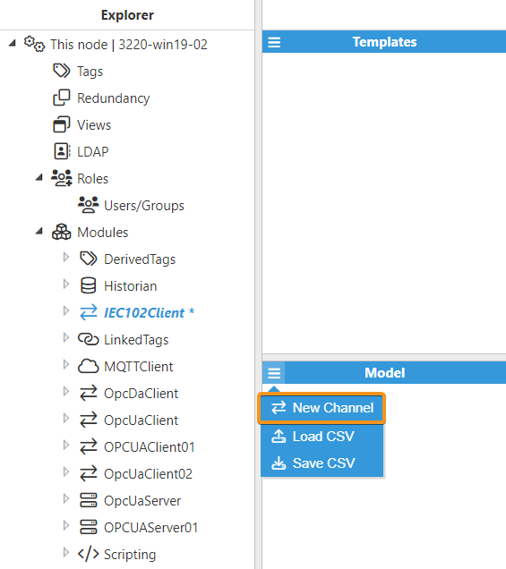
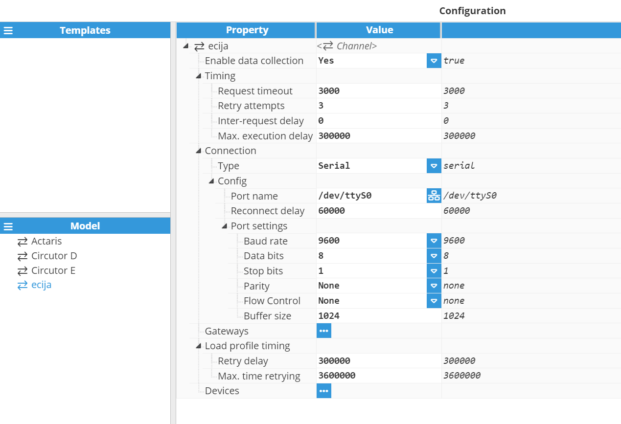
The first step when configuring a connection to the meter is to create a new channel. A channel represents the physical medium of connecting one or more devices. In this example, the name of the new channel is COM1, since it is communicating to the meter through an optical probe connected to serial port 1.
Each channel requires the following parameters to be set:
Enable data collection: When Disabled, the channel will remain inactive. The default value is set to Enabled.
Timing:
Request timeout: Time waiting for a valid response before retrying or moving to the next request, displayed in milliseconds. The valid range is 100ms to 600,000ms. The default value is 3,000ms.
Retry attempts: Number of communication retries before considering the target device to be unreachable and moving to the next request. The valid range is 0 to 100. The default value is 3, meaning that for each unresponsive request, the driver will make a total of 4 attempts (1 initial request and 3 retries).
Inter-request delay: Time between a valid response and the next request, displayed in milliseconds. This parameter may be used when a target device fails due to receiving the requests too quickly. The valid range is 0ms to 600,000ms. The default value is 0ms, which means that the next request will be sent as soon as a valid response has been received.
Max. execution delay: Maximum time that the associated tags quality should remain set to Good while an update is paused because the driver is busy or the channel is occupied by another application being connected to the devices in this channel through a gateway (if any). All associated tags will automatically be set to Uncertain when this time expires. This value is expressed in milliseconds. A value of 0 will disable this limit, allowing any data updates on this channel to be delayed and tags to retain a Good quality status indefinitely whilst other applications are connected through the gateways in this channel.
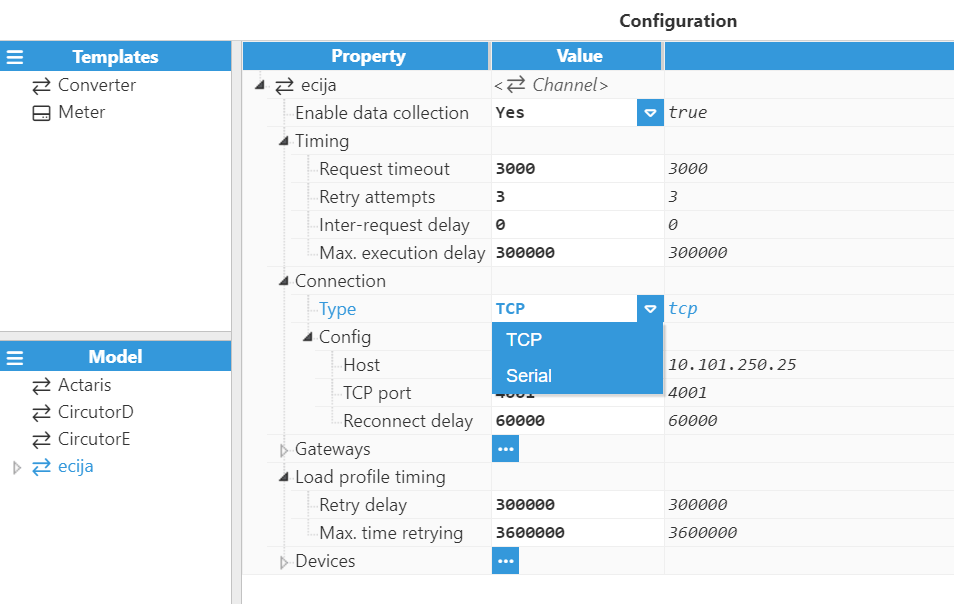
Connection:
Type: Defines the connection type.
TCP: Connects via a TCP socket.
Serial: Connects via a serial port.
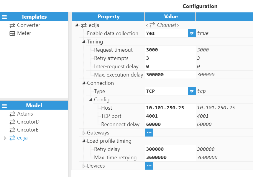
Each TCP channel includes the following parameters:
Host: Hostname or IP address of the target device.
TCP port: TCP port of the target device. The valid range is 1 to 65535. The default value is 4001.
Reconnect delay: Time before attempting to re-open a failed connection, displayed in milliseconds. The minimum value is 1,000ms. The default value is 60,000ms.
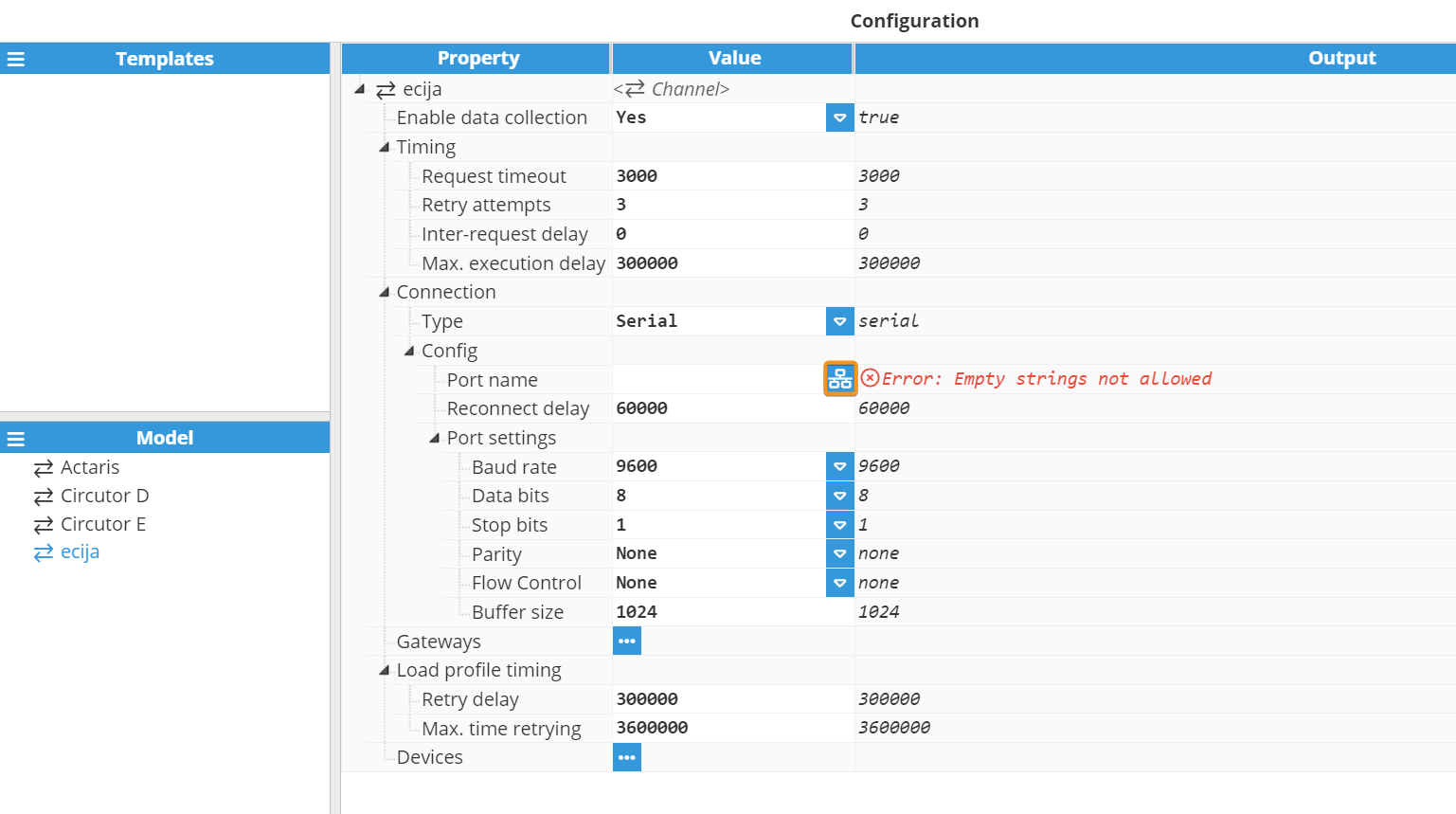
A serial channel includes the following parameters:
Port name: Serial port as displayed by the operating system. For example, if N3uron is running on Windows, valid port names would be COM1, COM2, and so forth. If running on Linux, valid port names would be /dev/ttyS0, /dev/ttyS1, and so forth.
Note:
The dropdown menu for serial port selection is available from N3uron version V1.21.7 onwards.
.png)
Reconnect delay: Time before trying to re-open a failed serial port, displayed in milliseconds. The minimum value is 1,000ms. The default value is 60,000ms.
Port settings:
Baud rate: Serial port transfer speed. Valid values are 110, 300, 1200, 2400, 4800, 9600, 19200, 38400, 57600 or 115200. The default value is 9600.
Data bits: Number of data bits per data word. Valid values are 5, 6, 7, or 8. The default value is 8.
Stop bits: Number of stop bits per data word. Valid values are 1 or 2. The default value is 1.
Parity: Data parity type. Valid options are none, even, mark, odd, or space.
Flow control: Enables the use of RTS/CTS (RS232) and RTS (RS485/RS422) control lines.
Buffer size: Serial communication buffer capacity. Valid range from 128 to 65536. The default value is 1024.
Gateways
Sometimes the port used to connect to the electrical meter must also be used by other applications, for instance for downloading the load profile. In this case, concurrent access to the port would cause collisions and communication errors. Adding a gateway to a channel permits a third-party application to access the meter whilst avoiding these issues.
The gateway on a channel listens to a TCP port and waits for any connections. When a third-party application connects, communication of all devices in this channel is paused, permitting a transparent connection between the application and any device in the channel. Once the application disconnects from the gateway, the driver will resume communication with the devices.
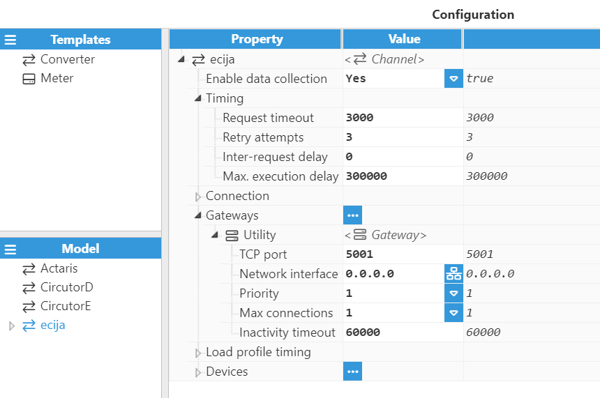
Configuration of a gateway includes the following parameters:
TCP port: The gateway listens to this port for any incoming connections. The selected port must not be used by any other gateway or application on the same machine. The valid range is 0 to 65535. The default value is 5001.
Network interface: Permitted interface for incoming connections.
0.0.0.0 allows connections from any network interface available within the machine.
127.0.0.1 or localhost only allows connections from local applications.
Use a specific IP address for a network card in the machine to only allow connections from this interface.
Priority: The priority of this gateway over the rest of the gateways on this channel. The valid range is 1 (highest priority) to 10 (lowest priority). The priority must be different for each gateway sharing the same channel. The default value is 1.
Max connections: The number of maximum concurrent connections supported. For future use, only 1 connection is permitted in this version. If more connections are required, another gateway should be set up.
Inactivity timeout: When an application is connected but remains inactive (no traffic), it will automatically be disconnected from the gateway after this time. This allows data collection to be resumed in order to continue to update any tags associated to this channel. This value is expressed in milliseconds. The default value is 60,000ms. A value of 0 will disable this functionality, stopping any applications from being automatically disconnected from the gateway, even if this application remains inactive indefinitely.
Load Profile Configuration
Note:
This feature is available from N3uron version 1.21.5.
The IEC 102 Client module allows automated load profile downloads from energy meters. The following configuration parameters determine the management of the download process:
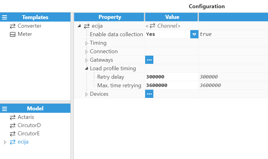
The load profile timing configuration settings contain the following options:
Retry delay: Specifies the delay time, in milliseconds, before requesting a load profile again after an unsuccessful request. The default value is 30000ms. The valid range is from 30000ms (5 minutes) to 3600000ms (1 hour).
Example: If the Retry delay is 5 minutes, the driver will send the request again after 5 minutes when the load profile request fails.
Max. time retrying: Defines the maximum time trying to retrieve a specific load profile register before considering it unavailable, marking it as <null> with quality Bad - Device failure, and moving to the next register. The default value is 360000ms.
Device Configuration
Each channel can connect to one or more electrical meters. A typical example of a channel containing one single device would be a direct TCP or serial connection to an IEC-102 device. An example of multiple devices in the same channel would be when several IEC-102 devices with different link addresses are connected within the same serial bus.
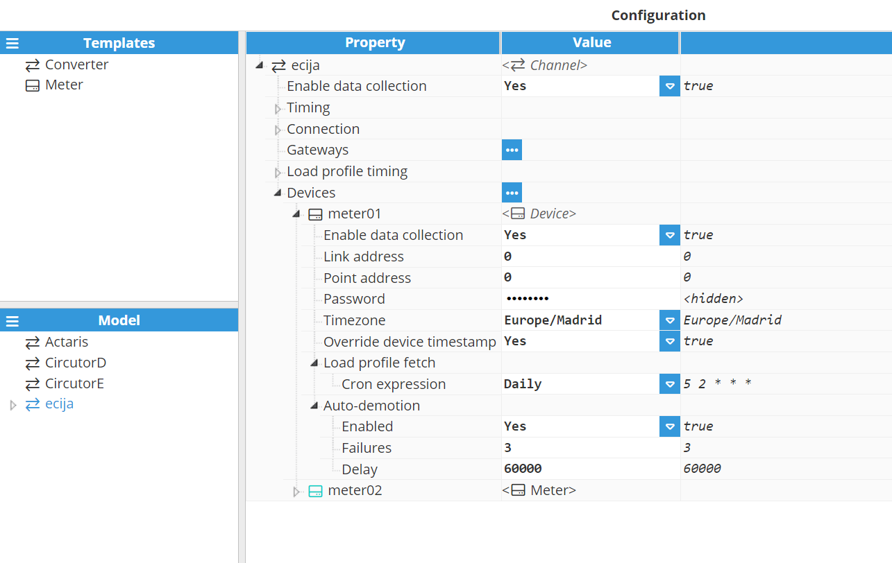
The device configuration settings contain the following options:
Enable data collection: Enables or disables data collection on the specified device. When Disabled, the channel will remain inactive. The default value is set to Enabled. If Disabled, data will not be sent to the device and the quality status of tags will remain as Bad – Uninitialized.
Link address: In IEC-102, each device must have a unique 16-bit address. This parameter specifies the IEC-102 link address of the target device. The valid range is 0 to 65535. The default value is 0.
Point address: Specifies the point address of the target device. The valid range is 0 to 65535. The default value is 0.
Password: Specifies the password required to access the device in read-only mode.
Timezone: Specifies the location timezone of the device.
Europe/Madrid
Atlantic/Canary
Africa/Ceuta
Override device timestamp: Allows the use of local timestamps instead of device timestamps.
Note:
Override device timestamp is available from N3uron version 1.21.7.
Load profile fetch: The IEC 102 Client module allows scheduling load profile downloads from energy meters.
Note:
The Load profile fetch is available from N3uron version 1.21.5
Note:
The load profile data is periodically downloaded based on the Cron Expression schedule. Each download spans from the last retrieved date to the current time. The start date of the next download can be modified using the tag 'Next request timestamp'.
Cron Expression:
Cron Expression: This field will require you to provide or select a cron expression to define the desired schedule. Readers can find further information at crontab.guru. For example, 0 3 * * * would schedule the task to run at 3 AM every day. It is also possible to select a predefined cron expression:
Every 15 minutes.
Hourly.
Daily.
Weekly.
Monthly.
Auto-demotion: Defines whether a device should be temporarily set to "off-scan" when not responding. If set to "off-scan", read requests will not be sent to the device, and any data associated with these read requests will automatically remain as "bad quality" while demoted. By placing a non-responsive device offline for a specific time period, the driver can continue to optimize communications with other devices in the same channel. Once this demotion period has been reached, the driver will re-attempt to communicate with the non-responsive device. If the device is responsive, it will be set to "on-scan". Otherwise, the "off-scan" time period will restart after the specified number of failures has been reached.
Enabled: When set to Enabled, if the specified number of successive failures is reached, data collection for this device will be set to “off-scan” during the specified interval.
Failures: Specifies how many consecutive rounds of request timeouts and retry attempts must occur before the device is set to "off-scan". The minimum value is 1. The default value is 3.
Delay: Time the device is set to "off-scan" for when the max consecutive failures value has been reached. When the specified interval expires, the driver will reset the device to "on-scan" and allow another communication attempt to be made. The minimum value is 1,000. The default value is 60,000 milliseconds.
Tag Configuration
The channel and device configuration options define the settings to be applied when establishing connections to the target device. After configuring these options, users will be able to create and configure any tags associated with data received from IEC-102 electrical meters, as seen in the following example:
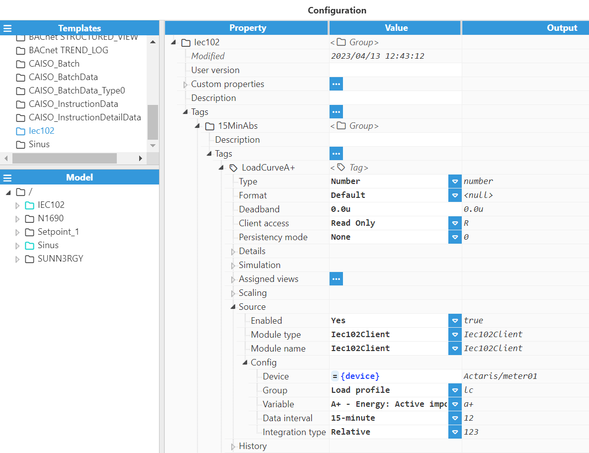
Source configuration settings contain the following parameters:
Enabled: When Disabled, tags won’t be updated with the values received from the device, but instead, will essentially act as memory tags. When set to Enabled, the tag value will be continuously updated with the values received from the field device. The default value is set to Disabled.
Module type: Defines the driver type used to retrieve values from the field. In this example, Iec102Client must be selected from the drop-down menu. If Iec102Client does not appear in the drop-down menu, this means that this driver has not been installed on this machine yet and must therefore be installed.
Module name: Defines the IEC 102 Client instance created.
Config:
Device: This refers to the device that has already been created in previous steps and will act as the data source. It should be referenced using the following format: channel/device.
Group: Defines the tag data group.
Instant values: current values of voltages, power, energy, currents and power factor.
Variable: Defines the electrical signal assigned to the tag, according to the IEC 60870-5-102 protocol specification. The following signals are available:
Energy: Active imported (kWh)
Energy: Active exported (kWh)
Energy: Reactive Q1 (kVArh)
Energy: Reactive Q2 (kVArh)
Energy: Reactive Q3 (kVArh)
Energy: Reactive Q4 (kVArh)
Power: Active total (kW)
Power: Reactive total (kVAr)
Power: Power factor total
Power: Active phase 1 (kW)
Power: Reactive phase 1 (kVAr)
Power: Power factor phase 1
Power: Active phase 2 (kW)
Power: Reactive phase 2 (kVAr)
Power: Power factor phase 2
Power: Active phase 3 (kW)
Power: Reactive phase 3 (kVAr)
Power: Power factor phase 3
V-I: Current phase 1 (A)
V-I: Voltage phase 1 (V)
V-I: Current phase 2 (A)
V-I: Voltage phase 2 (V)
V-I: Current phase 3 (A)
V-I: Voltage phase 3 (V)
Note:
The Device: Timestamp variable is available from N3uron version 1.21.7
Device: Timestamp
Scan rate: Poll interval for the specified tag, displayed in milliseconds. The minimum value is 100ms. The default value is 5,000ms.
Load profile: Allows retrieval of the load profile from the meters.
Variable: Defines the meter measures assigned to the tag, according to the IEC 870-5-102 protocol specification. The following measures are available:
A+: Exported Active Energy (kWh)
A-: Imported Active Energy (kWh)
Ri+: Reactive Energy in Q1 (kVArh)
Rc+: Reactive Energy in Q2 (kVArh)
Ri-: Reactive Energy in Q3 (kVArh)
Rc-: Reactive Energy in Q4 (kVArh)
Reserved field 1: Reserved
Reserved field 2: Reserved
Next request timestamp: Timestamp used as the starting point for the next load profile request. After a successful read, this value is automatically updated to the timestamp of the last record retrieved. Users can manually modify this value to change the starting point for the next retrieval, allowing targeted access to specific historical data.
Note:
There is a separate Next request timestamp for each combination of Data Interval and Interrogation Type, allowing each to be managed independently.
For example, if a client is reading both the 15-minute and daily load profiles, different tags with the Variable: Next request timestamp can be configured, one for the 15-minute profile and another for the daily profile.
Data Interval:
15-minute: Data obtained corresponds to the 15-minute load profile of the device.
1 hour: Data obtained corresponds to the 1-hour load profile of the device.
1 day (15-min. data): Data obtained corresponds to a daily interval (calculated by the device based on 15 minutes of data).
1 day (hourly data): Data obtained corresponds to a daily interval (calculated by the device based on 1-hour data).
Integration type:
Relative: The data collected correspond to values obtained during the interval.
Absolute: The data collected corresponds to absolute incremental readings of the meter.
Examples:
15-minute - Relative: provides the data relative to 15-minute intervals. For instance, the energy imported during a 15-minute interval.
15-minute - Absolute: Provides the absolute readings of the meter at 15-minute intervals. The difference between two consecutive absolute readings corresponds to the relative value for this interval.
1 day (15-minute) - Relative: provides the data corresponding to 1-day intervals accumulated based on 15-minute values. For instance, the energy imported during a 1-day interval.
1 day (15-minute) - Absolute: Provides the absolute readings of the meter at 1-day intervals. The difference between two consecutive absolute readings corresponds to the relative value for this interval.
Refer to this link for more detailed information on creating tags.