Note:
Before starting the configuration, a new module instance must be created. Click here for more information about creating Module instances.
Note:
This module is available from N3uron version 1.21.7.
Module Configuration
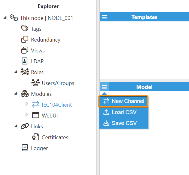
As shown in the previous screenshot, multiple connections can be created in the Model panel by clicking on the burger menu icon. Each connection is named Channel. See below for an explanation of the different configuration options.
Channel Configuration
.png)
A channel represents the physical medium that will be used for communication between N3uron and remote IEC 104 devices. Each channel has the following parameters:
Setting | Description |
|---|---|
Enable data collection | When Disabled , the connection will remain inactive and all associated tags will remain as Bad-Uninitialized. The default value is set to Enabled . |
Connection
Setting | Description |
|---|---|
Host | Hostname/IP address of the target device. |
TCP Port | TCP port number for the connection. |
Reconnect delay | Delay before attempting to reopen the connection after a failed attempt, in milliseconds . |
Protocol settings
Setting | Description |
|---|---|
Common address size | Determines the number of bytes (or octets) used for the common address. The default setting is 2 .
|
Cause of transmission size | This parameter specifies the number of bytes in the Cause of Transmission (COT) field of an IEC 60870-5-104 data packet. It can be 1 or 2 bytes. The second byte represents the originator's address. In this way, when the COT size is 2 it includes the originator address (the address of the IEC 60870 client) in the messages, while the originator address is not included in the messages when the size is set to 1 . The default setting is 2 bytes. |
Originator address | This parameter specifies the second byte of the Cause of Transmission (COT) field in an IEC 60870-5-104 data packet . The Originator Address is used to identify the source of the data packet . This is useful in systems with multiple controlling station s, or when there are dual-mode stations that can act as both a master and a slave. The valid range for the Originator Address parameter is 0 to 254 . The default setting is 0 . |
K | The K parameter, also known as the maximum unacknowledged transmitted APDUs , defines the maximum number of unconfirmed APDUs transmitted to the other station without waiting for an acknowledgment (ACK) for each APDU. The default setting is 12 .
|
W | The W parameter, also known as the maximum unacknowledged received APDUs , defines the maximum number of APDUs received from the remote station before it is required to send an acknowledgment (ACK) indicating that it has successfully received all the APDUs. This setting works in conjunction with T2 to limit how often the client acknowledges APDUs. The default setting is 8 .
|
Timing
Setting | Description |
|---|---|
T1 | Maximum time to receive the acknowledge message (ACK) to a transmitted APDU (Application Protocol Data Unit). If the ACK is not received within the specified T1 timeout period , the sender assumes that the APDU has either been lost or corrupted. As a result, the client closes the current connection and initiates a reconnection. The default setting is 15000ms .
|
T2 | The T2 parameter, also known as the APDU acknowledgment timeout , defines the time to wait before sending a supervisory APDU ACK response indicating that it has successfully received the APDU. The default setting is 10000 ms .
|
T3 | The T3 parameter, also known as the idle timeout , defines the maximum amount of time that a communication link can remain idle before a TEST APDU frame is transmitted to verify the connection's integrity. The default setting is 20000 ms .
|
T3 timeout | The T3 timeout defines de time to wait for the device to respond to a test frame. If the device does not respond in time, the connection will be terminated. The default setting is 20000 ms . |
Device Configuration
Once a Channel has been configured, a remote IEC 104 device can be added.
To create a new Device, you can click on the Devices button under Channel and select New Device.
When selecting New Device, begin by assigning a name, as illustrated in the image below.
Note:
Even though it's uncommon, the specification allows for a gateway that enables multiple devices with a single connection.
.png)
.png)
Once the device is created, you can configure the following parameters:
Setting | Description |
|---|---|
Enable data collection | Enable or disable data collection on this device. When disabled , no data will be sent to the device and associated tags will remain as Bad - Uninitialized . |
Write completion COT | Selects the Cause of Transmission (COT) required to consider a write command or interrogation successfully completed.
This parameter only affects the command types listed above. Analog commands (C_SE) and Bit-string commands (C_BO) are always considered complete after receiving an ActConf because ActTerm is optional for these command types according to the specification.
|
Common address of ASDU | The Common Address of ASDU parameter, also known as the COA , specifies a unique identifier for the outstation or remote device from which APDUs are received. The valid range is 0 to 254 or 65534 , depending on whether the Common address size setting is set to one or two octets. The default setting is 3 . |
Interrogation
Note:
Interrogation settings must be set up to regularly request data from the server. If there's no interrogation, and the server isn't set to send updates regularly, the client won't get any data. As a result, the tags in the client app will remain in a "bad quality" state showing that the data is unavailable.
.png)
Setting | Description |
|---|---|
Interrogation group | The Interrogation Group (IG) parameter in the IEC 104 protocol defines a logical grouping of data objects within an outstation or remote device. This grouping enables efficient data retrieval by allowing a client or master station to request data from multiple data objects with a single interrogation command.
|
Rate | Sets the rate at which interrogation APDUs are sent to the outstation. The default value is 60000ms. |
.png)
Tag Configuration
Note:
For additional details on Supported ASDUs, please refer to the Appendix.
The channel and device configuration parameters define the settings for establishing connections to slave devices. Once these elements are configured, users can proceed to create and configure tags associated with the data received from IEC 104 devices, as illustrated in the example below:
Source
Setting | Description |
|---|---|
Enabled | When Disabled , tags won't be updated with the values received from the server, but instead, will essentially act as memory tags. When set to Enabled , the tag value will be continuously updated with the values received. The default value is set to Disabled . |
Module type | The type of the module used to retrieve the tag's value, quality and timestamp. |
Module name | Name of the module instance used to obtain the tag's value, quality and timestamp. |
Config
Note:
Before N3uron version 1.22.4, only Direct Operate was supported for client-to-server commands. From version 1.22.4 onward, Select-Before-Operate (SBO) can also be configured individually for each tag. Select the mode that matches the command execution model supported by the outstation. To write values, ensure that the tag is configured as Read/Write.
Note:
Please note that the majority of RTUs or Outstations, do not automatically provide feedback through the same IOA used to send commands; instead, they often utilize a different IOA for feedback. Starting with N3uron version 1.21.11, you can configure separate IOA addresses for sending commands and receiving feedback within the tag configuration.
Setting | Description |
|---|---|
Device | Devices are specified using the format <channel>/<device_name> . Ensure the device is created and configured within the IEC104 Client module connections. For example, to connect to an IEC104 field device with channel name Channel01 and device name Device01 , use Channel01/Device01 . |
Read IOA | Specifies the Information Object Address (IOA) used to retrieve data for this tag. The IOA uniquely identifies a specific data object within an outstation or remote device. By assigning a separate Read IOA, the system can independently receive feedback, enabling more efficient data management and clearer monitoring of data retrieval processes.
|
Data type
Selects the type of data received from the outstation.
Setting | Description |
|---|---|
Single point |
|
Single command |
|
Double point |
|
Double command |
|
Step position |
|
Bit String |
|
Bit String command |
|
Normalized value |
|
Normalized value command |
|
Scaled value |
|
Scaled value command |
|
Floating point |
|
Floating point command |
|
Variable
This parameter defines the specific information to be extracted from the data received and assigned to the tag value. Available options for all data types include:
Common variables:
Setting | Description |
|---|---|
Value | Reads the current value of the data point. |
Cause of transmission (COT) | Reads the reason for the transmission of this APDU . |
Qualifier (Invalid) | Reads the invalid bit of the qualifier, indicating whether the value is valid ( 0 ) or invalid ( 1 ) due to abnormal conditions. |
Qualifier (Not topical) | Reads the not topical bit of the qualifier, indicating whether the value is current ( 0 ) or outdated ( 1 ) . |
Qualifier (Substituted) | Reads the substituted bit of the qualifier, indicating whether the value is from the original source ( 0 ) or substituted ( 1 ). |
Qualifier (Blocked) | Reads the blocked bit of the qualifier, indicating whether the value is available ( 0 ) or blocked ( 1 ). |
Step Position Specific variables:
Setting | Description |
|---|---|
In transit flag | Reads the value of the In transit flag of the data point, which is the 8th bit of the step position value. It indicates whether the position is changing ( 1 ) or stable ( 0 ). |
Value (Raw) | Reads the raw value received from the server. This includes the whole byte, which consists of the first seven bits representing the value and the 8th bit representing the In-transit flag . |
Qualifier (Overflow) | Reads the overflow bit of the qualifier, indicating if an overflow has occurred. |
Normalized Value Specific variables:
Setting | Description |
|---|---|
Value (Normalized) | Reads the value of the data point after calculating the normalized value. |
Value (Raw) | Reads the raw value received from the server before calculating the normalized value. |
Qualifier (Overflow) | Reads the overflow bit of the qualifier, indicating if an overflow has occurred. |
Scaled Value Specific variables:
Setting | Description |
|---|---|
Qualifier (Overflow) | Reads the overflow bit of the qualifier, indicating if an overflow has occurred. |
Bit string Specific variables:
Setting | Description |
|---|---|
Value | This allows you to access and read the value of a specific bit within the 32-bit string. You need to specify the bit position ( 0-31 ) to read its current value. |
Value (Raw) | Accesses the entire 32-bit string, allowing for both reading of the complete set of bits in one operation. |
Qualifier (Overflow) | Reads the overflow bit of the qualifier, indicating if an overflow has occurred. |
Write
The following settings apply when a Command data type is selected.
Note:
Select-Before-Operate is supported from N3uron version 1.22.4
Setting | Description |
|---|---|
Write mode |
|
Write IOA | Specifies the Information Object Address (IOA) used to send commands. A separate Write IOA can be configured when the outstation uses a different IOA to provide read feedback. This enables commands to be sent through the Write IOA while feedback is received through the configured Read IOA. |
Pulse type | Specifies the pulse type applied when writing Single Commands and Double Commands.
|
Refer to this link for more detailed information on creating tags.