This module is available from N3uron version 1.22.0.
Module Configuration
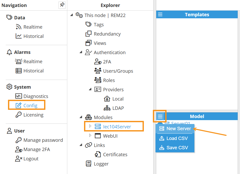
As shown in the screenshot to create a new Server follow this steps:
Navigate to System → Config → Modules → Iec104Server, or the name provided to the IEC 104 Server instance.
In the Model panel, click the menu (≡) and choose New Server to add additional IEC 104 server instances. You can also Load CSV or Save CSV to import or export the model configuration. See below for an explanation of the different configuration options.
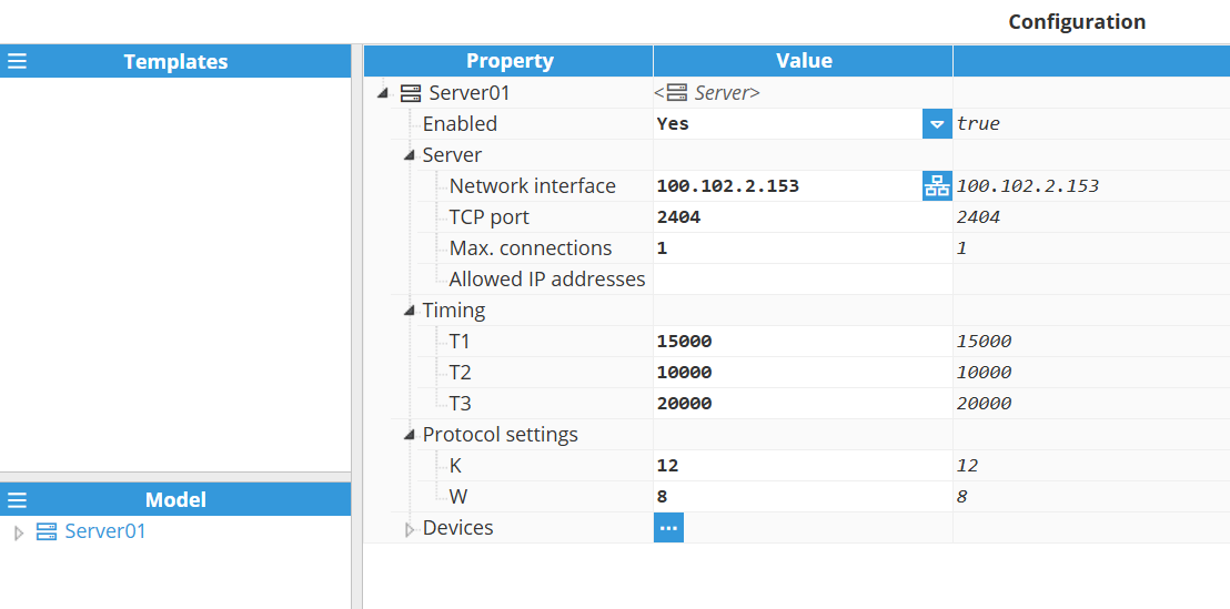
Server Configuration
A server represents the physical medium to which one or more slave devices can be linked. Each server requires the following settings to be configured.
Setting | Description |
|---|
Enabled | Enables or disables the IEC 60870-5-104 server instance. When disabled, the server will not be initialized or accept any client connections. |
Server | Network interface: Specifies the IP address of the network interface to which the server should bind. Use 0.0.0.0 to listen on all available interfaces. TCP Port: Specifies the TCP port on which the server will listen. Max. connections: Specifies the maximum number of simultaneous client connections that the server will accept. Exceeding this limit will result in new connection attempts being rejected. The maximum configurable value is 100 connections. Allowed IP addresses: Specifies the maximum number of simultaneous client connections that the server will accept. Exceeding this limit will result in new connection attempts being rejected. The maximum configurable value is 100 connections.
|
Timing | T1: Specifies the maximum time (in milliseconds) the server will wait for an acknowledgement (ACK) after transmitting an APDU (Application Protocol Data Unit). If no ACK is received within this timeout, the APDU is considered lost or corrupted, and the server will retransmit it. Default value: 15000 ms.
Example: If T1 is set to 15000 ms, the server expects an ACK from the client within 15 seconds after sending data. If the ACK is not received within this period, the server assumes a communication failure and retries the transmission. This mechanism helps maintain reliable communication in case of network delays or packet loss. T2: The T2 parameter, also known as the APDU acknowledgement timeout, defines the maximum time the server can wait before sending a supervisory APDU to acknowledge a received APDU. The default setting is 10000 ms.
Example: With a T2 timeout of 10000 milliseconds, a server receiving APDUs from the client will wait for up to 10000 milliseconds before sending an acknowledgement. This allows the server to bundle multiple acknowledgements into a single message, increasing communication efficiency. The server will send the acknowledgement sooner if the maximum number of unacknowledged APDUs (defined by the W parameter) is reached before the T2 timeout expires. T3: The T3 parameter, also known as the idle timeout, defines the maximum amount of time a communication link can remain idle (without any APDU exchange) before a TEST APDU frame is transmitted to verify the connection's integrity. If the client does not respond to this test frame within the T1 timeout period, the server will assume the connection is lost and will terminate it. The default setting is 20000 ms.
Example: With a timeout of 20000 milliseconds, a test frame will be sent to the client if no APDUs are exchanged within this timeframe. The receipt of any APDUs will reset this timer, ensuring that communication remains active and the connection is not dropped due to inactivity.
|
Protocol settings | K: The K parameter defines the maximum number of unconfirmed APDUs that can be transmitted before waiting for an acknowledgement. This value acts as a flow control mechanism for the TCP connection. The default setting is 12.
Example: With a K value of 12, the server can transmit up to 12 APDUs to the client before it must receive a confirmation. If the client sends an acknowledgement before this limit is reached, the counter is reset, and the server can continue sending. If the limit is reached, the server must pause transmission and wait for a supervisory APDU from the client. W: The W parameter defines the maximum number of APDUs that can be received from a remote station (client) before the server is required to send an acknowledgement. This acts as a receiver-side flow control. The default setting is 8.
Example: With a W value of 8, the server will hold off on sending an acknowledgement to the client until it has received 8 unacknowledged APDUs or the T2 timeout period has elapsed. At that point, the server will transmit a supervisory APDU to acknowledge all received APDUs, which helps optimize network traffic.
|
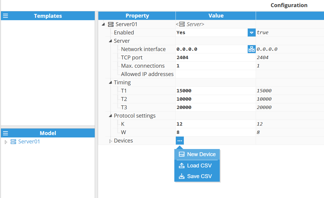
Device Configuration
After configuring the Server instance, add a Device: in the server’s Devices section, click the 3-dotted icon → New Device, as illustrated in the image below. You can also Load CSV or Save CSV to import or export device configuration.
Once the device is created, you can configure the following settings.
Setting | Description |
|---|
Enabled | Toggles the active state of this IEC 60870-5-104 slave/outstation instance. When disabled, the slave/outstation will not respond to any client requests. |
Common address of ASDU | The Common address of ASDU (COA) uniquely identifies this device within the IEC 60870-5-104 network. This value is included in all outgoing APDUs. Valid range: 1 to 65534. |
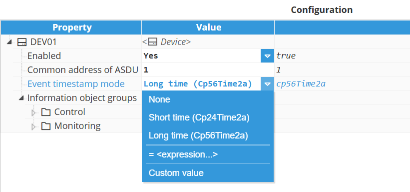
Event timestamp mode | Specifies the timestamp format used when the device sends event messages. This setting determines which ASDU (Application Service Data Unit) types are used for event transmission.
This parameter applies only to events. Since commands write a value directly to the tags, not an update, the datatype of the command sent by the client must not include a time tag.
The available modes are: None: Events are sent without a timestamp. Uses ASDU types that do not include a time tag, such as: M_SP_NA_1 – Single-point information M_DP_NA_1 – Double-point information M_ME_NA_1 – Measured value, normalized value M_BO_NA_1 – Bitstring of 32 bits.
Short time (Cp24Time2a): 24-bit timestamp format including minute, second, and millisecond. This is a short time tag; the receiving system must infer the date and hour. Uses ASDU types such as: M_SP_TA_1 – Single-point information with 24 bits short-time tag. M_DP_TA_1 – Double-point information with 24 bits short-time tag. M_ME_TA_1 – Measured value, normalized value with 24 bits short time tag. M_BO_TA_1 – Bitstring of 32 bits with 24 bits short time tag.
Long time (Cp56Time2a): 56-bit timestamp format with full date and time (year, month, day, hour, minute, second, millisecond). This long-time tag provides complete and precise time information. Uses ASDU types such as: M_SP_TB_1 – Single-point information with 56 bits long-time tag. M_DP_TB_1 – Double-point information with 56 bits long-time tag. M_ME_TD_1 – Measured value, normalized value with 56 bits long-time tag. M_BO_TB_1 – Bitstring of 32 bits with 56 bits long-time tag.
|
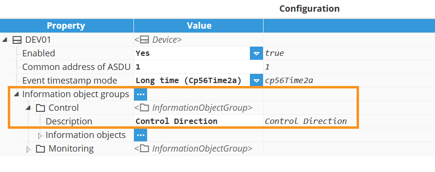
Next, create an Information Object Group for targeted interrogations. In the Device, open Information object groups, click the 3-dotted icon → New InformationObjectGroup, as shown below. You can also Load CSV or Save CSV to import or export information object groups configuration.
.png)
Information object group.
After creating an information object group, add information objects to it by selecting the group and opening Information Objects. Then click the 3-dotted icon → New InformationObject. You can also Load CSV / Save CSV to bulk import or export points.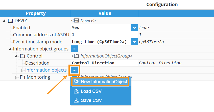
Information object
Setting | Description |
|---|
Tag | Select the source tag that this information object will expose through the IEC 60870-5-104 server. The data type of the selected tag must be compatible with the configured ASDU type to maintain data integrity. |
Data type | Specifies the IEC 60870-5-104 data type used to encode and transmit the value of this information object. The selected type must match the source tag's data type to maintain data integrity. |
Information object address | The Information Object Address (IOA) serves to uniquely identify each data point or information object within a device or station. The address must be a unique integer for each information object associated with a given data type. The range of possible IOA values is from 1 to 16777215 (3 octets). |
Interrogation group (used for monitoring or accessing information objects) | Associates this information object with a specific interrogation group. When a client issues an interrogation request for a group, the server will respond with all information objects assigned to that group. This feature makes data handling more efficient by letting clients request specific subsets of data instead of retrieving all data points. Available options: None: The information object is not assigned to any specific interrogation group (1-16). It will be included in the General Interrogation (a full data refresh request) and will also be sent as an unsolicited event whenever its value changes. Interrogation groups 1 through 16.: Assigns the object to a specific group (1–16). The server will return the object when that particular group is interrogated by the client. Additionally, it will be included in the General Interrogation (a full data refresh request) and will also be sent as an unsolicited event whenever its value changes.
|
If the chosen ASDU type differs from the source tag's format, a lossy conversion may be applied (e.g., converting a floating-point value to a single point will result in a Boolean value).
This data type represents a two-bit status, which is more robust than a single point and can indicate four different states. The value exposed by the IEC 60870-5-104 server as a double point depends on the data type and value of the source tag, according to the following logic:
From a Boolean tag:
From a Number tag:
0.0 converts to Intermediate (00).
1.0 converts to Off (01).
2.0 converts to On (10).
3.0 or any other numerical value converts to Invalid (11).
From a String tag:
The string "false" (case-insensitive) converts to Off (01).
The string "true" (case-insensitive) converts to On (10).
Any other string value converts to Invalid (11).
From a Null value:
IEC 104 Server Full Product Details