As shown in the previous screenshot, multiple connectionscan be created in the Model Panel by clicking on the burger menu icon. Each connection is named Channel. See below for an explanation of the different configuration options.
Channel Configuration
A channel represents the physical medium of connecting one or more devices. Each channel has the following settings.
Setting
Description
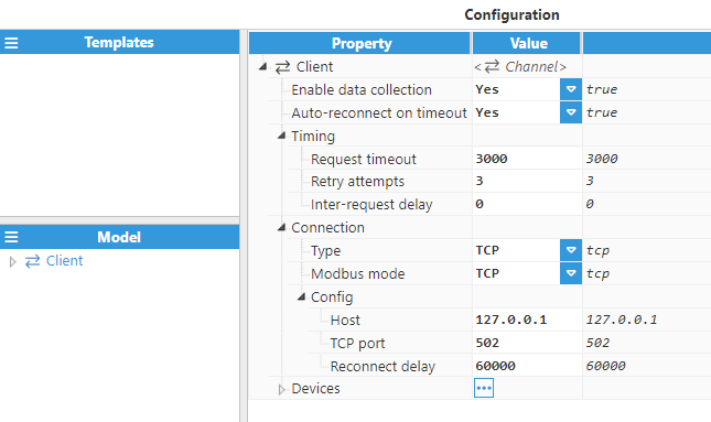
Enable data collection
When disabled, the connection will remain inactive and all associated tags will remain as Bad-Uninitialized. The default value is set to Enabled.
Auto-reconnect on timeout
If enabled, the channel will automatically be reconnected whenever all configured devices fail to respond within the specified time slot.
Timing
Request Timeout: Maximum amount of time to wait for a valid response, displayed in milliseconds. The valid range is 100ms to 600,000ms. The default value is set to 3,000ms.
Retry attempts: Number of communication retries before considering the target device as unreachable. The valid range is 0 to 100. The default value is 3.
Inter-request delay: elay before sending subsequent requests to the target device, displayed in milliseconds. The valid range is 0ms to 600,000ms. The default is 0ms.
Connection
Type: Specifies the connection type that will be established:
TCP: TCP socket.
Serial: Serial Port.
Modbus mode: Specifies the Modbus working mode.
TCP: Modbus TCP.
RTU encapsulated: Modbus RTU encapsulated over TCP.
RTU: Modbus RTU.
Config - Connection typeTCP
Host: Hostname or IP address of the target device.
TCP port: Determines which TCP Port to connect to. Valid values range from 1 to 65535.
Reconnect delay: Time before trying to re-open the connection after a failed attempt, displayed in milliseconds. The minimum value is 1,000ms.
Config - Connection type Serial
Port name: Serial port as displayed by the operating system. For example, if N3uron is running on Windows, valid port names would be COM1, COM2, and so on. On Linux, valid port names would be /dev/ttyS0, /dev/ttyS1, and so forth.
Reconnect delay: Time before trying to re-open the serial port after a failed attempt, displayed in milliseconds. The minimum value is 1,000ms.
Port settings:
Baud rate: Serial port transfer speed in milliseconds. Valid values are 110, 300, 1200, 2400, 4800, 9600, 19200, 38400, 57600, or 115200.
Data bits: Specifies the number of data bits per data word. Valid values are 5, 6, 7, or 8.
Stop bits: Specifies the number of stop bits per data word. Valid values are 1 or 2.
Parity: Specifies the type of parity for data. Valid values are None, even, mark, odd, or space.
Flow Control: Enables the use of RTS and DTR control lines. There are 3 options: None, RTS/CTS (RS232), and RTS (RS485/RS422).
Buffer size: Specifies the Serial communication buffer capacity. The valid range is 128 to 65536.
The image below shows the channel configuration for the TCP connection type.
The image below shows the channel configuration for the Serial connection type.
Device Configuration
Each channel can have one or more devices. A typical example of a channel containing a single device would be a direct TCP or serial connection to a Modbus slave. An example of multiple devices in the same channel would be when Modbus slaves are connected within the same serial bus.
Set a name for the device and proceed with the configuration. In this case, the device name is Device01.
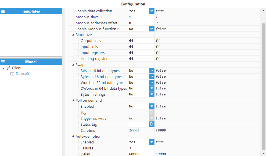
The table below displays the device settings.
Setting
Description
Enable data collection
When disabled, the channel will remain inactive. The default value is set to Enabled.
Modbus Slave ID
Specifies the slave number of the device. The valid range is 0 to 255. The default value is 1.
Modbus addresses offset
Specifies the offset value to be added to all Modbus addresses defined in the device. For example: if Offset=2, this means that every tag read from this device will add 2 to its configuredaddress value. Valid values are in the range of -65536 to 65536.
Enable Modbus function 6
If enabled, function 6 (for writing a single register) will be used. Otherwise, function 16 will be used.
Block size
Output coils: Sets the maximum block size request, in bits, for the output coils. Valid values are within the range 1-2000.
Input coils: Sets the maximum block size request, in bits, for the input coils. Valid values are within the range 1-2000.
Input registers: Sets the maximum block size request, in bytes, for the input registers. Valid values are within the range 2-240.
Holding registers: Sets the maximum block size request, in bytes, for the holding registers. Valid values are within the range 2-240.
Swap
Bits in 16-bit data types: If enabled, the bits from each 16-bit data block will be swapped. This only takes affect when reading or writing bit values in a word.The rest of the data types (16, 32, and 64) are not affected by this configuration. The MSB (most significant bit) will become the LSB (least significant bit) and vice versa.
Bytes in 16-bit data types: If true, the bytes for each 16-bit data block will be swapped. For example, if the data received is 00AA, this will be turned into AA00.
Words in 32-bit data types: If true, the words (16 bits) within a 32-bit data block will be swapped. For example, if the data received is 0000 AAAA, this will be turned into AAAA 0000.
DWords in 64-bit data types: If true, each double word (32 bits) within a 64-bit data block will be swapped. For example, if the data received is 0000 1111 EEEE FFFF, this will be turned into EEEE FFFF 0000 1111.
Bytes in Strings: If enabled, the bytes for each 16-bit data block in a string will be swapped. For example, If the data received is 12345678, this will be changed into 21436587.
Poll on-demand
Enabled: Enables or disables the poll on-demand mechanism.
Tag: The selected tag will be monitored to enable or disable poll on demand for the device.
Trigger on write: If enabled, the poll on demand will be activated whenever a write is carried out on this device.
Status tag: Defined tag that shows whether this device has an active poll on-demand mechanism or not.
Duration: Time that the poll on-demand mode will be active for until it is automatically reset.
Auto-demotion
Defines whether data collection from a device should be paused after several successive failures to prevent affecting other devices on the same channel.
Enabled: When set to enabled, the device will be paused until the time specified in the Delay field has elapsed.
Failures: Specifies the number of successive failures for demoting the device. The minimum value is 1 and the default value is 3.
Delay: Determines the time period before the device will be demoted once the maximum amount of failures has been reached and until a new communication attempt takes place. The minimum value is 1,000 and the default value is 60,000 milliseconds.
Tag Configuration
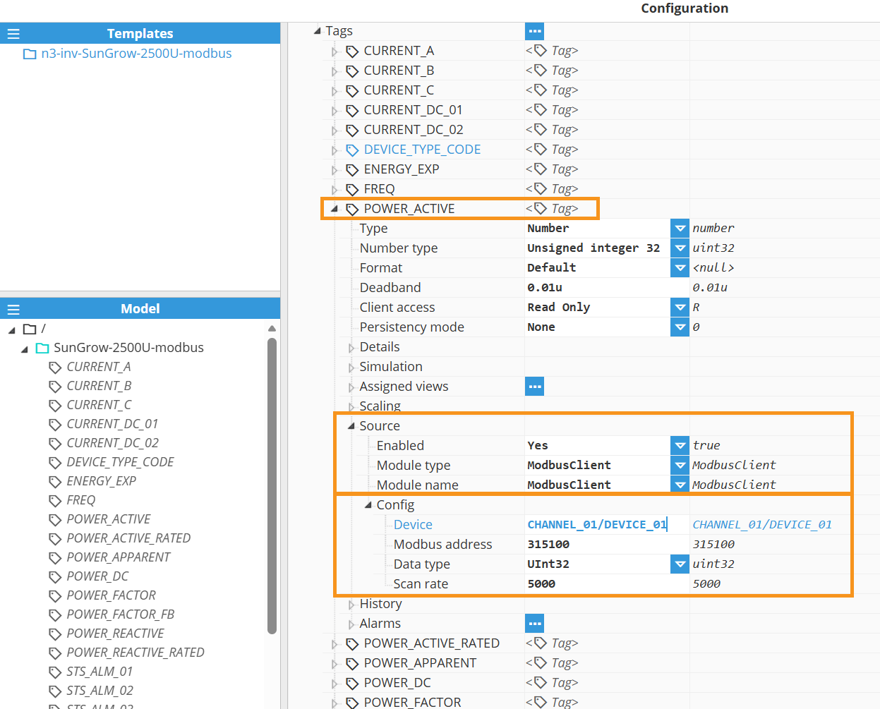
After configuring the channel and device, tags can be created to read data from the Modbus device. The Source section contains the mandatory settings that link each tag to its data source(channel/device) within the previously configured Modbus Client module instance. These settings are listed below.
Setting
Description
Source
Enabled:When disabled, tags will not be updated with the values received from the device, but instead, will essentially act as memory tags. When set to Enabled, the tag value will be continuously updated with the values received from the field device. The default value is set to Disabled.
Module type: Defines the driver type used to retrieve values from the field. In this example, ModbusClient must be selected from the drop-down menu. If ModbusClient does not appear in the drop-down menu, it means that this driver has not yet been installed on this machine and therefore, must be installed.
Module name: Introduce the name of the Modbus Client module instance that we previously created.
Config:
Device: Specify the previously created device that will act as the data source. The format must be Channel/Device.
Modbus Address: Specify the address according to the device memory map. The supported functions are listed in the table below.
Data type: Introduce the relevant type for the driver to decode the incoming binary data into an actual value
Boolean
UInt16
Int16
UInt32
Int32
Int32-M10K
UInt64
Int64
Float32
Double64
String
Scan rate:Poll interval for the tag, displayed in milliseconds. The minimum value is 100ms. The default value is 5000ms.
Function name
Code
Hex
Read Discrete Inputs
02
0x02
Read Coils
01
0x01
Write Single Coil
05
0x05
Read Input Register
04
0x04
Read Holding Register
03
0x03
Write Single Register
06
0x06
Write Multiple Registers*
16
0x10
Note:
Function 16 is supported, however, multiple writes are not possible, thus it works like function 6 (write single register).
Modbus Addressing:
The table below shows some examples of the available Modbus address types. To read or write to a specific bit within an input or holding register, simply append a period and the location of the bit.
.png)
.png)
.png)
.png)