Connecting to an Inverter using Modbus Client
In this example, the Modbus Client module is used to connect to an inverter acting as a slave over TCP. The inverter has the following memory map:
Template: PV inverter | ||||||
Communication protocol: Modbus TCP | ||||||
Tag same Modbus | Modbus Address | Data type | Access | Units | Scaling | Description |
ALARMS/FAN_ERROR | 400108.2 | boolean | R | 1 | Alarm: Fan diagnostics error | |
ALARMS/IGBT_HIGH_TEMP | 400108.3 | boolean | R | 1 | Alarm: High temperature in drive | |
ENERGY_TODAY_VAL | 400101 | Int32 | R | W/h | 0.1 | Energy generated on current day |
ERROR_CODE | 400103 | Int16 | RW | 1 | Error Code: 0 - No error, 1 - AC error, 2-DC error | |
FREQUENCY_VAL | 400104 | Int16 | R | Hz | 0.01 | Grid Frequency |
POWER_SP | 400105 | Int16 | RW | kW | 1 | Active power setpoint |
POWER_VAL | 400106 | Int16 | R | kW | 0.1 | Active power generated |
STATUS_CODE | 400107 | Int16 | R | 1 | Status code | |
Follow the below steps to set up the connection correctly:
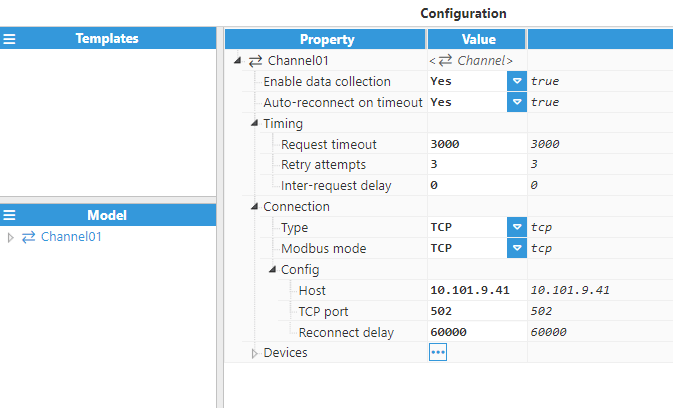
Step 1: After creating a Modbus Client module instance, a connection with the device needs to be configured, as depicted in the below image.
For this example, the following fields have been configured:
Host:10.101.9.42, which is the device's IP address.
TCP port: By default, port 502 is used.
Step 2: Once the connection has been set up, the device must be created and configured. In this example, a device has been created named Device01.
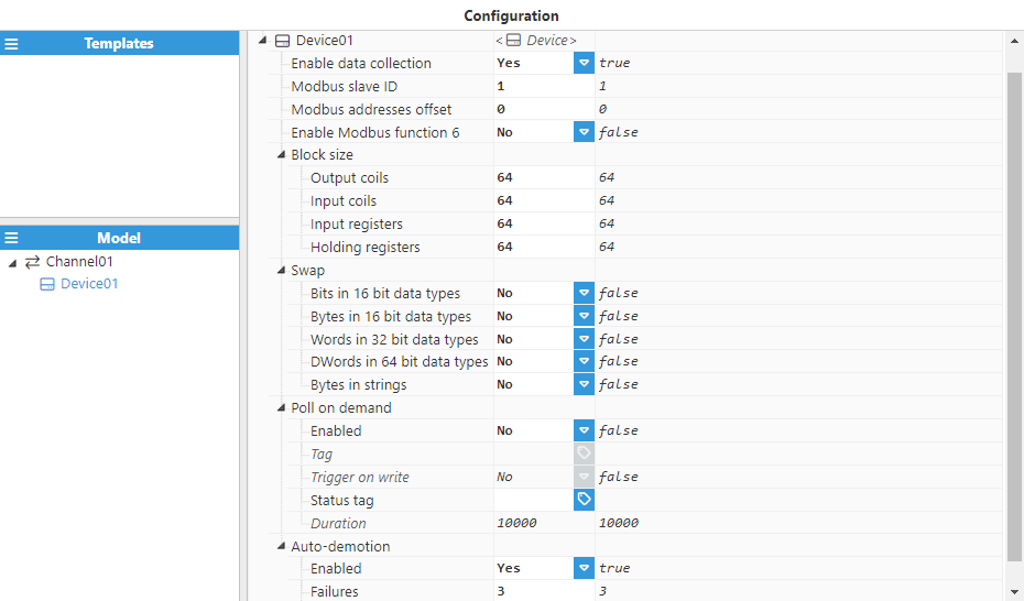
The remaining parameters have been left at their default settings. With the connection now established, we can proceed to create new tags based on the memory map outlined above.
Step 3: In the Explorer panel, select Tags. In the Model panel, create a new group and name it INV01.
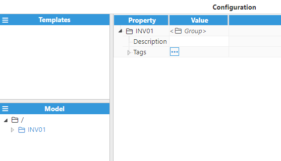
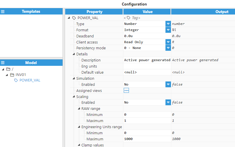
Step 4: Create a tag inside the group and name it POWER_VAL.
.png)
Step 5: Set the configuration parameters properly:
Type: Number.
Format: Integer.
Client Access: R.
Details:
Description: Active power generated.
Scaling:
Enabled: Yes.
Raw Range:
Minimum: 0.
Maximum: 1.
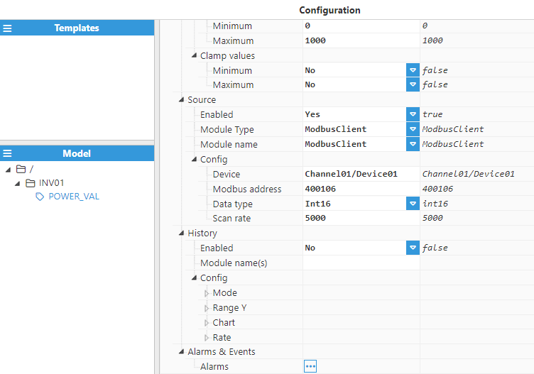
Source:
Enabled: Yes.
Module type: ModbusClient.
Module name: ModbusClient.
Config:
Device: This option must follow the format <channel>/<device>. In this case, Channel01/Device_01.
Modbus Address: The Modbus Address for the POWER_VAL is 400106, as shown in the memory map table.
Data type: Int16.
Create the remaining tags associated with the inverter by following the same procedure outlined above.
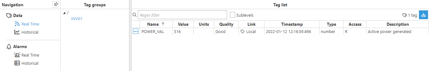
Now, go to the Data/Real-Time section in the Navigation panel, where you should be able to see the data read from the device.