Note:
Before starting the configuration, a new module instance must be created. Click here for more information about creating Module instances.
Channel Configuration
New channels can be created by selecting the Modbus Server instance from the Explorer tree menu.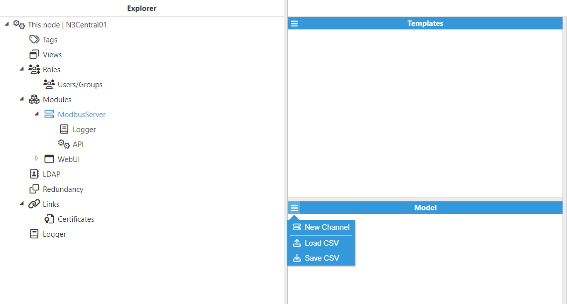
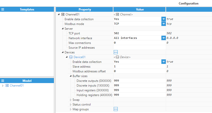
A channel represents the physical medium to which one or more slave devices can be linked. Each channel requires the following parameters to be configured: 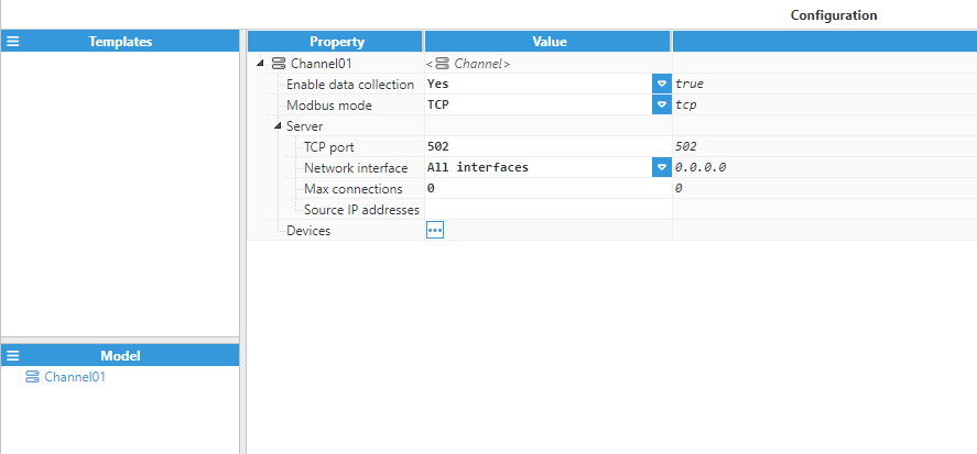
- Enable data collection: When disabled, the channel will remain inactive. The default value is set to Enabled.
- Modbus mode: Defines the connection mode. The available options are TCP and RTU encapsulated.Note:
- Modbus TCP uses a specific TCP/IP-based protocol structure with an MBAP (Modbus Application Protocol) header.
- Modbus RTU over TCP simply encapsulates the standard Modbus RTU frame within a TCP packet.
- Server:
- TCP port: TCP port of the target device. The valid range is 1 to 65535, the default port number is 502. This port may not be used by any other application on the same machine.
- Network interface: Specifies the interface via which the Modbus Server will be accessible. If set to All interfaces, the Modbus Server will listen to connections on all interfaces. If set to Localhost only, the Modbus Server will only listen to localhost connections. In addition to the above options, the IP address for a specific network interface can also be set to only allow connections from its own network.
- Max connections: The maximum number of TCP clients supported by this server. Set to 0 to disable the limit.
- Source IP addresses: Allows IP addresses to be whitelisted for incoming connections. Several IP addresses can be permitted using a comma-separated list. No restrictions are applied when left empty.
Device Configuration
Each channel can have one or multiple devices. 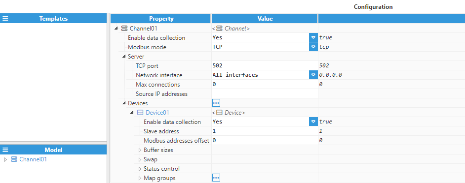
The device configuration settings contain the following options:
- Enable data collection: Enables or disables data collection on the specified device. When disabled, any request received from the Modbus master will be discarded with an exception response (0x0A - GATEWAY_PATH_UNAVAILABLE).
- Slave address: Specifies the 8-bit address of the slave device. The valid range is 0 to 255. The default value is 1.
- Modbus addresses offset: Offset to be added automatically to all Modbus addresses in this device. The valid range is -65536 to 65536.
- Buffer sizes:
- Discrete outputs (0XXXXX): Number of 1-bit discrete outputs to create in the internal memory area 0XXXXX. The valid range is 1 to 99999. The default value is 999.
- Discrete inputs (1XXXXX): Number of 1-bit discrete inputs to create in the internal memory area 1XXXXX. The valid range is 1 to 99999. The default value is 999.
- Input registers (3XXXXX): Number of 16-bit input registers to create in the internal memory area 3XXXXX. The valid range is 1 to 99999. The default value is 999.
- Holding registers (4XXXXX): Number of 16-bit holding registers to create in the internal memory area 4XXXXX. The valid range is 1 to 99999. The default value is 999.
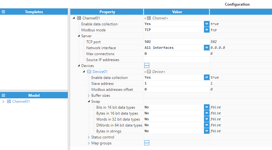
- Swap:
- Bits in 16-bit data types: When True, the bits of each 16-bit data block are swapped. This only affects the action of reading/writing bit values in a word. The rest of the data types (16, 32, and 64 data types) are not affected by this setting.
- Bytes in 16-bit data types: Swap bytes (8 bits) inside a 16-bit data block.
- Words in 32-bit data types: Swap words (16 bits) inside a 32-bit data block.
- DWords in 64-bit data types: Swap double words (32 bits) inside a 64-bit data block.
- Bytes in strings: Swap bytes (8 bits) inside a string data block.
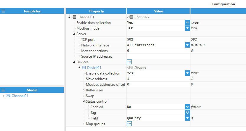
- Status control:
- Enabled: When enabled, the device status can be controlled from a tag’s value or quality. If the control tag’s quality is not Good or its value is not equal to 0, all requests received from the Modbus master will be discarded with an exception response (0x04 – SERVER_DEVICE_FAILURE).
- Tag: Path of the selected Tag for Status Control.
- Field: Tag field to bind to. If Quality is selected, the device status will be set to error when the target tag’s quality is not Good. If Value is selected, the device status will be set to error when the target tag’s value is not equal to 0.
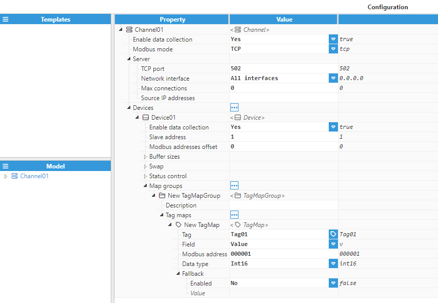
- Map groups:
- Tag maps:
- Tag: Target tag to obtain updates from and send write requests to.
- Field: Tag field to bind to. When Quality or Timestamp is selected, the data quality will be forced as GOOD_LOCAL_OVERRIDE, so that the fallback condition will never occur.
- Modbus address: Modbus address of the tag. The Offset value configured in the Modbus Device will be added to the value configured here.
- Examples:
- Coil: 000001
- Discrete Input: 100001
- Input Register: 300001
- Holding Register: 400001
- Bit within an Input Register: 300001.<bit> (bit from 0 to 15)
- Bit within a Holding Register: 300001.<bit> (bit from 0 to 15)
- String: 400001:<length> (length in bytes from 0 to 250)
- Examples:
- Data type: Instructs the driver how to encode the selected field into the corresponding binary data. If the selected field is Quality or Timestamp, the appropriate numeric or text version of its value will be used in order to match the selected data type.
- Examples:
- Quality - UInt16: 192
- Quality - String: GOOD_NOT_SPECIFIED
- Timestamp - UInt64: 1590747344497
- Timestamp - String: 2020-05-29T10:15:44.497Z
- Examples:
- Fallback:
- Enabled: When enabled, the configured fallback value will be used instead of the value of the selected tag whenever its quality is not Good. When the selected field is set to Quality or Timestamp, this setting will have no effect, since its associated quality will always be Good.
- Value: Fallback value to be written to the Modbus register when the selected tag is not in Good quality.
- Tag maps: