Exposing an Inverter data using Modbus Server
In this example, we are going to use Modbus Server to expose data coming from an ABB inverter that is being acquired through N3uron's Aurora Client module.
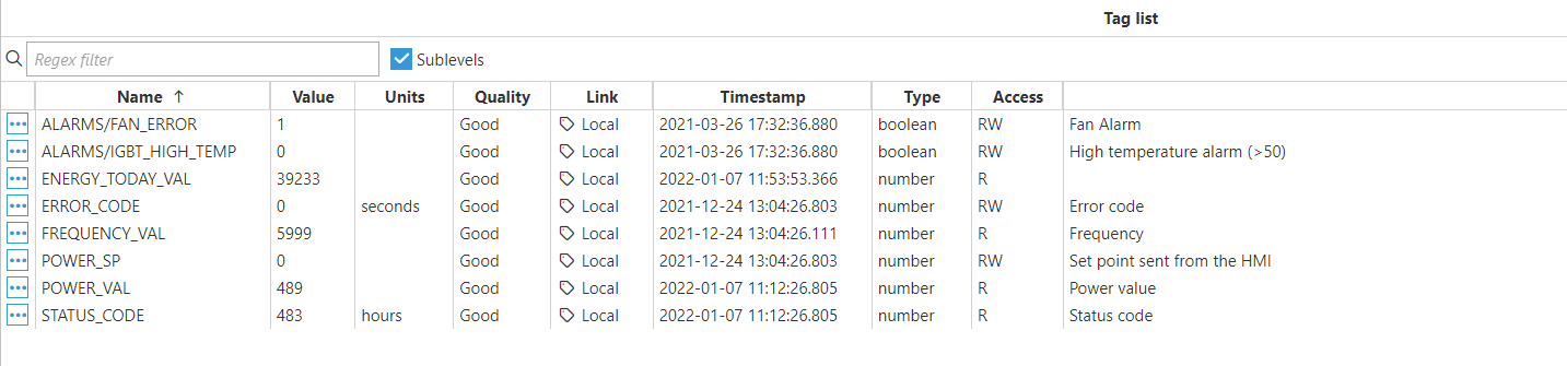
Below is the memory map that shall be configured in Modbus Server:
| Template: PV inverter | ||||||
| Communication protocol: Modbus TCP | ||||||
| Tag Name | Modbus Address | Data type | Access | Units | Scaling | Description |
| ALARMS/FAN_ERROR | 400108.2 | boolean | R | 1 | Alarm: Fan diagnostics error | |
| ALARMS/IGBT_HIGH_TEMP | 400108.3 | boolean | R | 1 | Alarm: High temperature in drive | |
| ENERGY_TODAY_VAL | 400101 | Int32 | R | W/h | 0.1 | Energy generated on current day |
| ERROR_CODE | 400103 | Int16 | RW | 1 | Error code: 0 - No error, 1 - AC error, 2 - DC error | |
| FREQUENCY_VAL | 400104 | Int16 | R | Hz | 0.01 | Grid frequency |
| POWER_SP | 400105 | Int16 | RW | kW | 1 | Active power setpoint |
| POWER_VAL | 400106 | Int16 | R | kW | 0.1 | Active power generated |
| STATUS_CODE | 400107 | Int16 | R | 1 | Status code | |
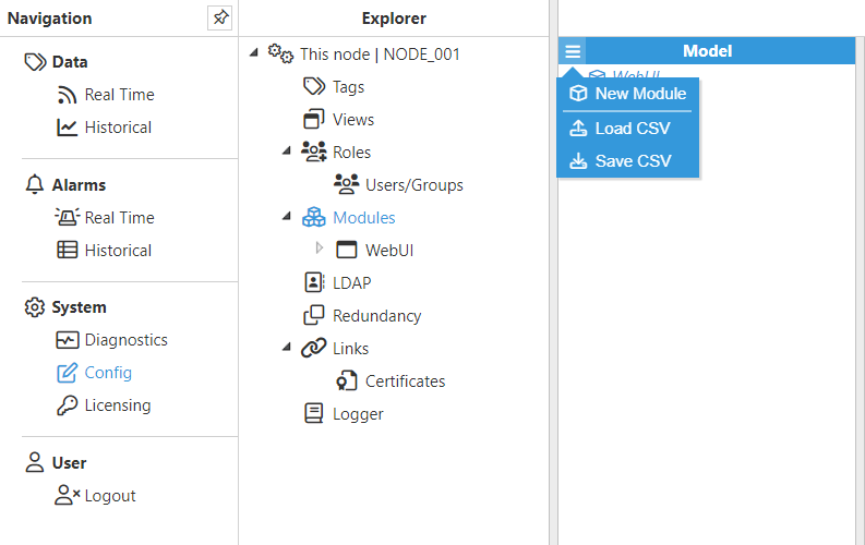
- Step 1: Add a new module in the "Modules" section, choose a name, and select "Modbus Server" in the "Module type" field.
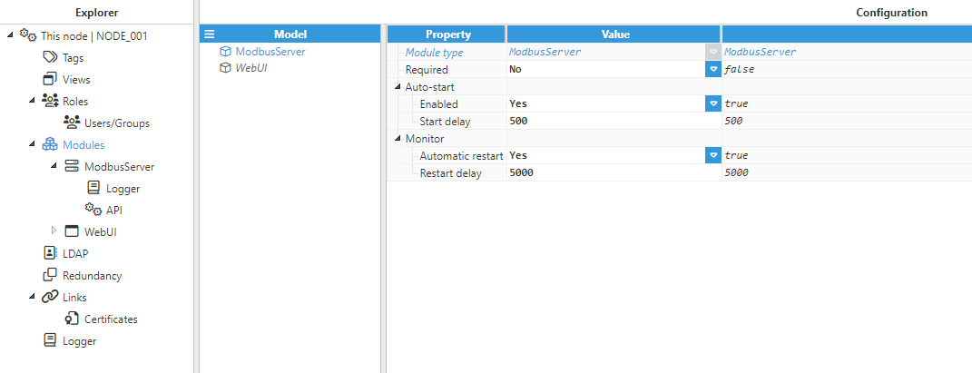
- Step 2: Configure the Logger and API for the Modbus Server module. In this example, the default configuration has been left unchanged, since in most cases, this is a valid configuration option.
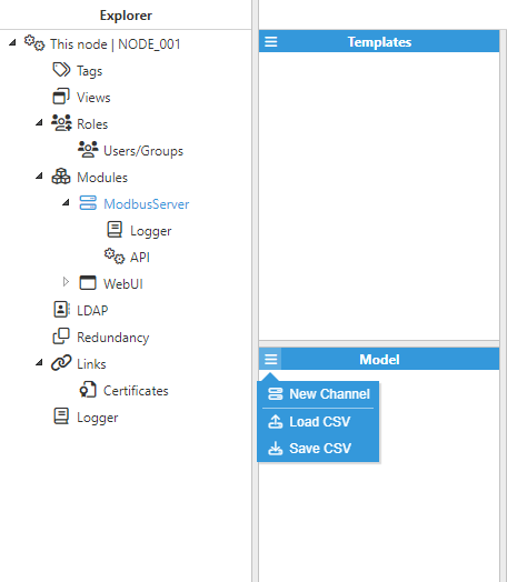
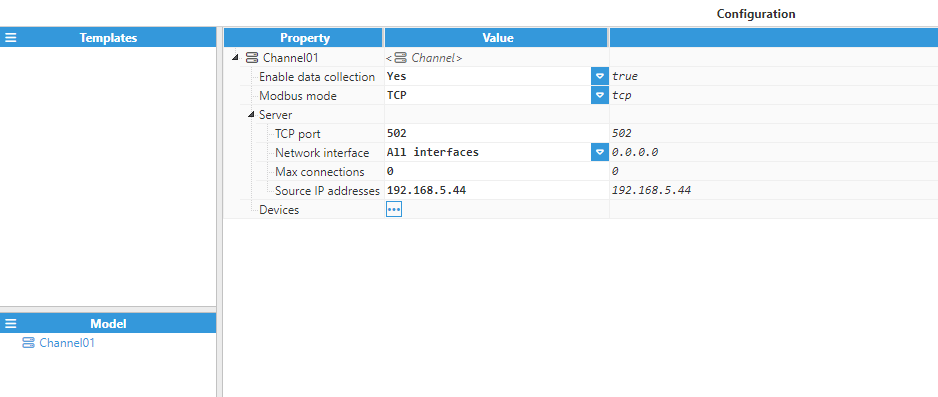
- Step 3: Add a new channel in the “Model” section and choose a name for it. The Source IP addresses field can be left empty in order to allow all IP addresses for incoming connections. However, specifying the Source IP address is strongly recommended, as this adds an extra layer of security.
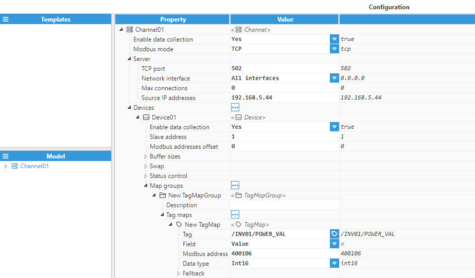
- Step 4: Add a new device in the “Configuration” section and configure the device.
.png)
- Step 5: Next, add a "Map group" and set its configuration.
- Step 6: Finally, add a "Tag Map", and start creating all the tags from the Memory Map (shown above). The following Figures show the configuration settings for an Int16 and a Boolean tag respectively. The rest of the tags should be configured similarly.
.png)