Device Configuration
.png)
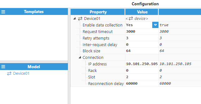
As shown in the previous screenshot, multiple connections can be created in the Model Panel by clicking on the burger menu icon. Each connection is named Device. See below for an explanation of the different configuration options.
- Enable data collection: When disabled, the connection will remain inactive and all associated tags will remain as Bad-Uninitialized. The default value is set to Enabled.
- Request Timeout: Maximum amount of time to wait for a valid response, displayed in milliseconds. The valid range is 100ms to 1,000,000ms. The default value is 3,000ms.
- Retry attempts: Number of communication retries before considering the target device as unreachable. The valid range is 0 to 100. The default value is 3.
- Inter-request delay: Delay before sending the next request to the target device, displayed in milliseconds. The valid range is 0ms to 1,000,000ms. The default is 0ms.
- Block size: Maximum block size request, in bytes. The valid range is 1 to 1024.
- Connection
- IP address: IP address of the target PLC.
- Rack: The number of the rack that the device is positioned in. The default is 0. The valid range is 0 to 255.
- Slot: The slot number assigned to the CPU. The default is 2. The valid range is 0 to 255.
- Reconnection delay: Time before trying to re-open the connection after a failed attempt, displayed in milliseconds. The minimum value is 1,000ms.
Tag Configuration
Device configuration parameters define the settings used for establishing a connection to a Siemens PLC. After configuring these elements, users will be able to create and configure all tags associated with the data received from the Siemens PLCs, as seen in the below example:
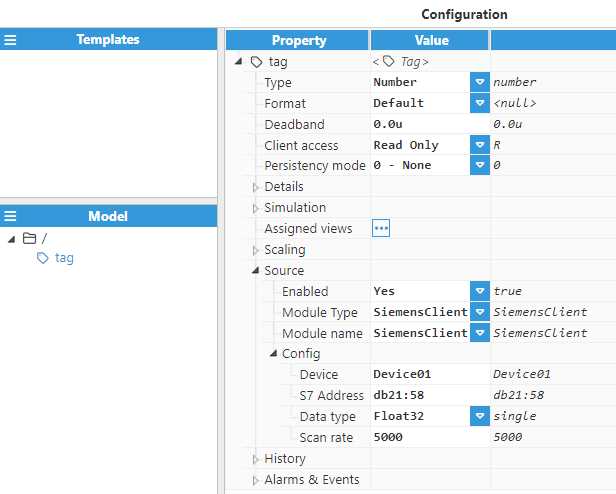
Tags require the following parameters to be configured:
- Source
- Enabled: When disabled, tags will not be updated with the values received from the device, but instead, will essentially act as memory tags. When set to Enabled, the tag value will be continuously updated with the values received from the field device. The default value is set to Disabled.
- Module type: Defines the driver type used to retrieve values from the field. In this example, SiemensClient must be selected from the drop-down menu. If SiemensClient does not appear in the drop-down menu, it means that this driver has not yet been installed on this machine and therefore, must be installed.
- Module name: Introduce the name of the previously created Siemens Client module instance.
- Config
- Device: Specify the previously created device that will act as the data source.
- S7 Address: Specify the tag's S7 address. Tag addresses are made up of two different components, Area and Offset.
| Area Syntax | |
| DataBlocks | db |
| Inputs | i |
| Outputs | o |
| Flags | m |
To form an address, you need to combine syntax for the desired Area and Offset in that area, which must be congruent with the Data type you assign to the tag. See some addressing examples in the below table.
| Tag type | S7 Address |
| Analog | m:00, i:00, o:00, db4:00 |
| Discrete | m:00.00, i:00.01, o:00.02, db4:00.7 |
| String | m:00:1, i:00:10, o:00:10, db4:00:100 |
- Data type: Select the relevant data type in order for the driver to decode the incoming binary data into an actual value. The available data types are as follows:
- Boolean
- Uint8
- INT8
- Uint16
- INT16
- Uint32
- INT32
- Uint64
- INT64
- Float32
- Double64
- String
- DTL
- Custom Expression
- Scan rate: Poll interval for the tag, displayed in milliseconds. The minimum value is 100ms.
Refer to this link for more detailed information on creating tags.