Module Configuration
.png)
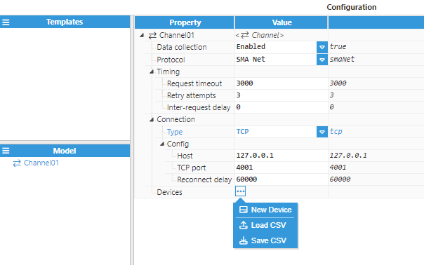
The SMA Client module allows the creation of multiple connections in the Model Panel by clicking on the burger menu icon. Each connection is named Channel. See below for an explanation of the different configuration options.
Channel Configuration
A channel represents the physical medium of connecting one or more devices. Each channel object has the following configuration options:
- Data collection: When disabled, the channel will remain inactive. The default value is set to Enabled.
- Protocol: Defines the communication protocol for communicating with devices.
- SunnyNet: Legacy SunnyNet protocol.
- SMA Net: SMA Net protocol. This is the recommended protocol (if supported by the device).
- Timing
- Request Timeout: Maximum amount of time to wait for a valid response, displayed in milliseconds. The valid range is 100ms to 1,000,000ms. The default value is 3,000ms.
- Retry attempts: Number of communication retries before considering the target device as unreachable. The valid range is 0 to 100. The default value is 3.
- Inter-request delay: Delay before sending the next request to the target device, displayed in milliseconds. The valid range is 0ms to 1000000ms. The default is 0ms.
- Connection:
- Type: Specifies the type of connection that will be established:
- TCP: TCP socket.
- Serial: Serial Port.
- UDP: UDP socket.
- Type: Specifies the type of connection that will be established:
When connecting via TCP, the following options are displayed:
- Config:
- Host: Hostname or IP address of the target device.
- TCP port: Sets the TCP Port to connect to during communication. Valid values range from 1 to 65535. The default value is 4001.
- Reconnect delay: Time before trying to re-open the connection after a failed attempt, displayed in milliseconds. The minimum value is 1,000ms.
The image below shows an example TCP channel configuration:
.png)
Serial channels offer the following options:
- Config:
- Port name: Serial port, as displayed by the operating system. For example, if N3uron is running in Windows, valid port names would be COM1, COM2 and so forth, whilst if running on Linux, valid port names would be /dev/ttyS0, /dev/ttyS1, etc.Note:The dropdown menu for serial port selection is available from N3uron version V1.21.7 onwards.
.png)
.png)
- Reconnect delay: Time before attempting to re-open the serial port after a failed attempt, displayed in milliseconds. The minimum value is 1,000ms.
- Port settings:
- Baud rate: Serial port transfer speed, displayed in milliseconds. Valid options are 110, 300, 1200, 2400, 4800, 9600, 19200, 38400, 57600, or 115200. The default value is 9600.
- Data bits: Specifies the number of data bits per data word. Valid options are 5, 6, 7, or 8.
- Stop bits: Specifies the number of stop bits per data word. Valid options are 1 or 2.
- Parity: Specifies the type of data parity. Valid options are None, Even, Mark, Odd, or Space.
- Flow Control: Enables the use of RTS and DTR control lines. There are 3 available options: None, RTS/CTS (RS232), and RTS (RS485/RS422).
- Buffer size: Specifies the Serial communication buffer capacity. The valid range is 128 to 65536. The default value is 1024.
- Port name: Serial port, as displayed by the operating system. For example, if N3uron is running in Windows, valid port names would be COM1, COM2 and so forth, whilst if running on Linux, valid port names would be /dev/ttyS0, /dev/ttyS1, etc.
The image below shows an example of the serial channel configuration:
.png)
UDP channels have the following configuration parameters:
- Config:
- Host: Hostname or IP address of the target device.
- UDP port: Sets the UDP Port for sending messages to. Valid values range from 1 to 65535. The default value is 24272.
The image below shows an example of the UDP channel configuration:.png)
Device Configuration
Each channel can have one or more devices associated to it. A typical example of a channel containing a single device would be a direct TCP or serial connection to an SMA slave. An example of multiple devices in the same channel would be when SMA slaves are connected within the same serial bus.
Set a name for the device and proceed with the configuration. In this example, the device name is Device01.
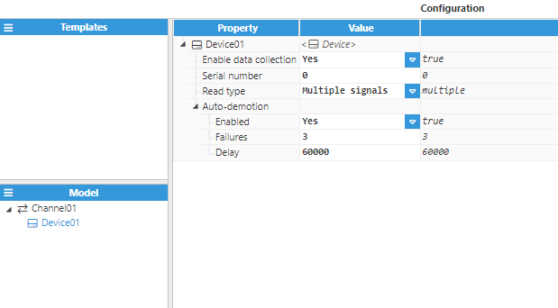
The configuration parameters are as follows:
- Enable data collection: When disabled, the channel will remain inactive. The default value is set to Enabled.
- Serial number: Specifies the serial number of the target device, as provided by the manufacturer.
- Read type: Establishes how the data will be read from the device.
- Single signals: Each signal shall be read independently of others. In other words, a one-to-one reading.
- Multiple signals: All signals belonging to a group and type will be read collectively in a single request. This mode speeds up the process and makes it faster. However, some devices might not be compatible with this mode.
Multiple signal readout is the default and optimal state. Single signal readout is only recommended if devices do not support multiple signal readout.
- Auto-demotion: Defines whether a device should be temporarily placed as “off-scan” when the device is not responding. If set to “off-scan”, read requests will not be sent to the device and any data associated with these read requests will automatically be set as “bad quality”. By placing a non-responsive device offline for a specific time period, the driver can continue to optimise its communications with other devices in the same channel. Once this demotion period has been reached, the driver will re-attempt to communicate with the non-responsive device. If the device is responsive, it will be placed as “on-scan”; otherwise, the off-scan time period will be restarted.
- Enabled: When set to enabled, the device will automatically be taken “off-scan” until it starts to respond again.
- Failures: Specifies how many successive cycles of request timeouts and retries can occur before the device is placed “off-scan”. The minimum value is 1. The default value is 3.
- Delay: Determines the demotion period and indicates how long the device should be placed “off-scan” when the value of the failure has been reached. When the specified period expires, the driver will place the device as “on-scan” and allow another communication attempt to be made. The minimum value is 1,000. The default value is 60,000 milliseconds.
At this point, the connection should be fully established.
Tag Configuration
The channel and device configuration fields define the settings used when establishing connections to SMA devices. After configuring these elements, users will be able to create and configure any tags associated with the data received from SMA devices.
Provide a name for the tag, in this case, tag is used. The following image shows an example configuration:.png)
The only mandatory settings that need to be configured are those contained within the source section, these parameters are listed below,
- Source:
- Enabled: If Enabled, this permits reading of tags from its source.
- Module type: Select the module type that will be used as the tag source.
- Module name: Determines the name of the previously created module that will act as a source for the tag.
- Config
- Device: Specifies which device will act as a data source. The device must be defined in the SMA Client module and the format must be Channel/Device.
- Channel name: The target channel name, as defined in the target device. The list of available channels can be found in /data/SmaClient/SERIAL_NUMBER.json within N3uron's installation folder, where SERIAL_NUMBER is the serial number of the device. In order for this list to be generated, at least one tag must be created, even if it points to an inexistent variable. If this file is not found, users will need to browse the device and generate the file containing all the signals provided by the device.
- Scan rate: Poll interval for the specified tag, displayed in milliseconds. The minimum value is 100ms. Only applicable when device mode is set to static polling.
The following file shows an example list of channels provided by an inverter,