API Configuration
API parameters define the communication settings between the module and N3uron's bootstrap.
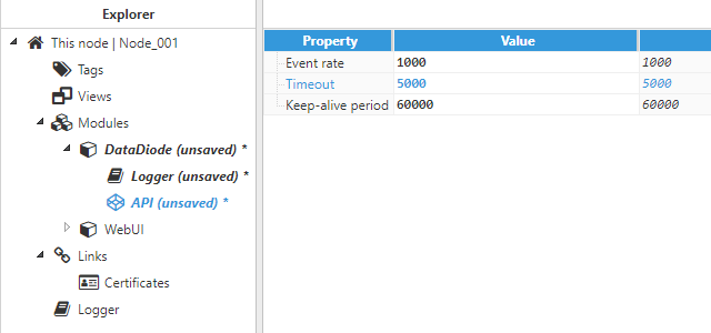 Figure 4: API parameters
The API configuration settings include the following parameters:
- Event rate: Determines the Event exchange rate between bootstrap and the module, displayed in milliseconds. The default value is 1,000ms with a minimum value of 100ms.
- Timeout: Maximum wait time for a response from bootstrap, displayed in milliseconds. The minimum value is 100ms and default value is 5,000ms. For nodes dealing with a large number of tags, this time can be increased to avoid timeouts when communicating with bootstrap.
- Keep-alive period: Time between keep-alive checks with bootstrap, displayed in milliseconds. Set to 0 to disable keep-alive checks for this module. The default value is 60,000ms. When the module fails to respond to keep-alive requests, bootstrap will automatically restart the module process.
Once the API parameters have been set, the configuration settings must be saved and the module needs to be restarted in order to apply the new values.
Logger Configuration
These parameters define how the module logs activity.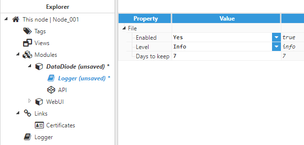 Figure 5: Logger configuration
Parameters:
- Enabled: When enabled, the module sends logs to a text file located at <installation_folder>/n3uron/log/<module_name>. The default value is set to enabled.
- Level: Level of detail provided in the information sent to the log file.
- Error: Only logs errors.
- Warning: Logs errors and warnings.
- Info (default): Logs errors, warnings, and general information messages.
- Debug: Logs most module activity for debugging and troubleshooting purposes.
- Trace: Logs full module activity. This mode may log large amounts of data and for this reason, it is not recommended for production environments.
- Days to keep: Log files are automatically deleted when they become older than the number of days specified in this section. The default value is 7 days.
Connection Configuration
By selecting DataDiode in the Explorer tree menu, users can create new channels to be connected to other nodes running in DataDiode. Each connection is established between a sender and a receiver. The sender forwards data in UDP packages in real-time and the receiver collects packages and extracts the data.
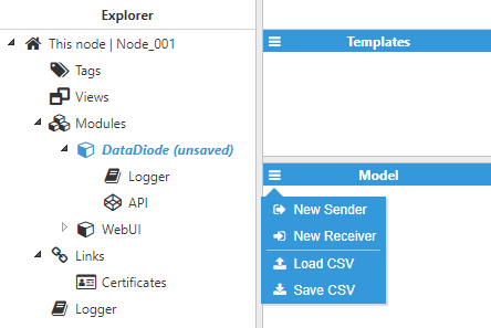 Figure 6: Creating new DataDiode connections
Sender Configuration
The Sender configuration section defines the settings for data sending.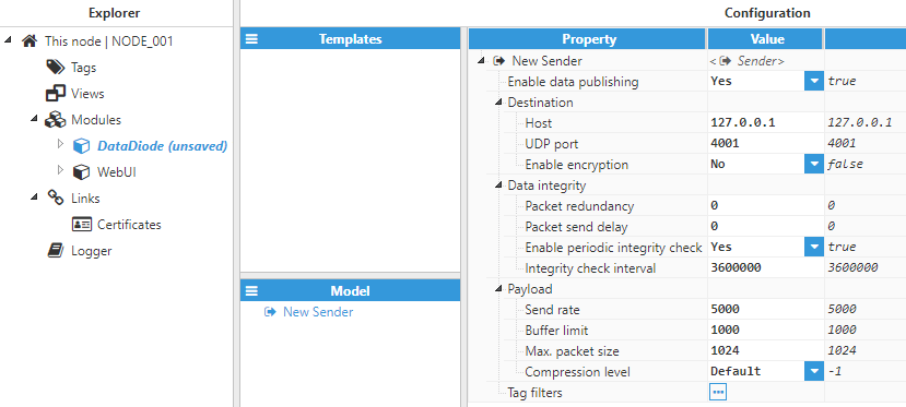 Figure 7: Sender configuration
Each sender requires the following parameters to be configured:
- Enable data publishing: When disabled, the sender will remain inactive. The default value is set to enabled.
- Destination:
- Host: Hostname or IP address of the receiver.
- UDP port: UDP port of the target device. The DataDiode receiver must be configured to use this port. The valid range is 1 to 65535. The default value is set to 4001.
- Enable encryption: Data transmitted can be encrypted for higher security using an aes-256-gcm algorithm. In order to use encryption, this setting must be enabled in both the sender and the receiver. The default value is set to disabled.
- Secret: When encryption is enabled, a text string must be provided to use as the key for encrypting the data. The same secret key must be used in the receiver in order to unencrypt the data.
- Data integrity:
- Packet resend: Since it’s possible for UDP packages to be lost, users can choose to force send all packages more than once in order to increase the reliability of data delivery. The valid range is 0 to 100.
- Packet send delay: Time between sending one datagram and the next, displayed in milliseconds. The valid range is 0 to 600,000ms.
- Enable periodic integrity check: Data is only sent to the receiver when there is a change. When periodic integrity check is enabled, a snapshot of the status of all tags is periodically sent to the receiver.
- Integrity check interval: Time between integrity snapshots (when enabled), displayed in milliseconds. The minimum value is 1,000ms, with a default value of 3,600,000ms (1 hour).
- Payload: Each payload contains all events since the last update. The speed and size of the updates can be modified.
- Send rate: Determines the interval between sending buffered tag events, displayed in milliseconds. The rate can become faster if the buffer limit is reached before the next interval. The minimum value is 1,000ms, with a default value of 5,000ms (5 sec).
- Buffer limit: Maximum number of events before a package is sent. When set to 0, it allows for an unlimited number of events in the buffer and only sends packages according to the send rate.
- Max. packet size: Maximum size of the packet, in bytes. When the packet is bigger, it will be split into smaller packages of up to the maximum size. Values higher than 4096 may result in an increase in dropped packets. The valid range is 500 to 65,000 bytes.
- Compression level: Compression compromise applied to the package:
- Default: Good compression ratio and good process speed. Recommended for most scenarios.
- Best compression: Higher compression ratio in exchange for a slower process speed. Recommended for scenarios with limited communication bandwidth.
- Best speed: Lower compression ratio and faster process speed. Recommended for scenarios with limited processing power.
- Tag filters: The information transmitted from the sender to the receiver can be fine-tuned using filters. Each filter may contain a tag or a group of tags to be included in the data sent to the receiver. It is also possible to apply Regex patterns to the tag path to create complex filters in just one step. When there are no associated filters with a sender, the values of all tags in this node are sent to the receiver.
Receiver Configuration
The Receiver configuration section defines the settings for data collection.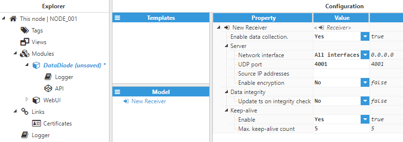 Figure 8: Receiver configuration
Receiver setup includes the following parameters:
- Enable data collection: When disabled, the receiver will remain inactive and all datagrams received (if any) will be discarded and any tags associated with this receiver will remain in bad quality. The default value is set to enabled.
- Server:
- Network interface: The receiver can listen for incoming datagrams to all network interfaces (0.0.0.0), only localhost (127.0.0.1), or to a specific interface assigned using its IP address.
- UDP port: The UDP port used to listen for incoming datagrams. Must be the same port used by the sender. The valid range is 1 to 65535. The default value is set to 4001.
- Source IP addresses: Permits IP addresses to be whitelisted for incoming datagrams. Several IP addresses can be permitted using a comma-separated list. All source IP addresses are permitted when empty.
- Enable encryption: Data transmitted can be encrypted for higher security using an aes-256-gcm algorithm. In order to use encryption, it must be enabled in both the sender and the receiver. The default value is set to disabled.
- Secret: When encryption is enabled, a text string must be provided to use as a key to encrypt the data. The same secret key must be used in the sender and the receiver to unencrypt the data.
- Data integrity:
- Update ts on integrity check: Once the snapshot of all the data status information has been received, the timestamp can be overwritten with the current time (set to Yes), or alternatively, the original timestamp received from the sender can be maintained (set to No). When the tags on the sender side are received from other nodes and the Store&Forward mechanism is enabled, update timestamp on integrity check must be disabled in order to avoid the timestamp from past values stored in remote nodes being overwritten.
- Keep-alive:
- Enable: Enables or disables the keep-alive mechanism. When enabled, if the 'Max. keep-alive count' is reached without receiving an update from the sender, the quality of any tags received from this sender will change to 'BAD'.
- Max. keep-alive count: Sets the maximum number of datagrams that can be missed before the server assumes the connection has dropped. Example: if the 'Send rate' of the sender is 5000ms and the 'Max. keep-alive count' in the receiver is 3, the receiver must receive updates every 5 seconds. If during 15 seconds (3 periods of 5 seconds) no updates are received, the receiver assumes the connection has dropped and the quality of the tags changes to BAD.
Tag Configuration
After configuring the Receiver, users will be able to create and configure any Tags associated to the data received from another N3uron node via the DataDiode module, as seen in the following example: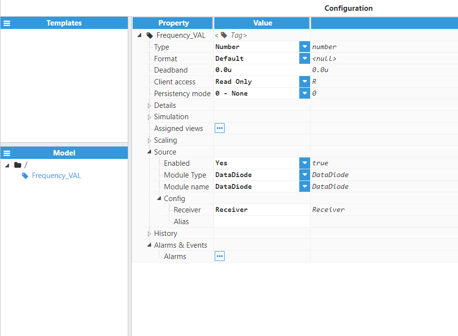 Figure 9: Receiver configuration
Source contains the following settings:
- Enabled: Enables the tag to be read from its source.
- Module Type: Specifies the source module type that will be used to read the tag.
- Module Name: Specifies the source module name that will be used to read the tag.
Config contains the following settings:
- Receiver: Specifies the receiver name (previously defined in Receiver configuration) that will become the datasource for the tag.
- Alias: Specifies the tag path of the target tag to monitor (located in the sending node). If left empty, the tag (located in the receiving node) must have the same tag path as the target tag (located in the sending node) in order for the data to be relayed.
Operating System Configuration
When there is a hardware data-diode between the sender and the receiver that only permits one-way communication, it may not be possible for the sender’s operating system to resolve the IP address of the receiver in order to translate it to its MAC address. In this case, mapping of the IP address to the MAC address can be manually added to the operating system’s ARP table in the sender machine.
For instance, the following command adds the host and also associates the IP address reciever_IP with the physical address receiver_MAC. The Physical address is provided as 6 hexadecimal bytes, separated by colons in Linux, or hyphens in Windows. Entry is permanent.
This command should work on most Windows and Linux systems, although the documentation on each user’s specific operating system should provide more details about how to manage the ARP table.
arp -s receiver_IP receiver_MAC