The following example involves 4 nodes: 2 nodes to initiate the connection (Remote Nodes) to the other 2 nodes which are receiving the connection (Central Nodes). In this way, both Central nodes will subscribe to the data collected by Remote nodes.
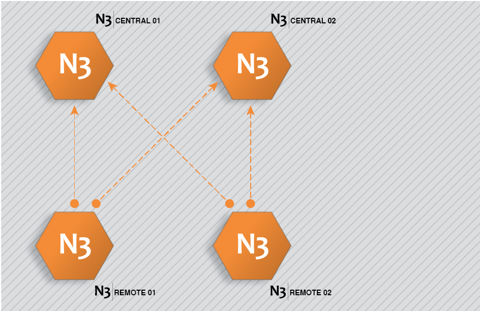
Figure 42. N3uron Links configuration example.
This architecture is created by completing the following steps:
Step 1: Configure N3Central01 and N3Central02 to receive incoming connections (Config => Links).
- Provide the name (N3Central01 and N3Central02). This name must be unique among all connected nodes.
- Enable incoming connections and configure the listening port (3001 by default).
- Create a specific connection for remote nodes N3Remote01 and N3Remote02 by setting tag subscription as “All” and publish view as none. This means that these nodes are now subscribed to all available tags in the remote nodes but won't be publishing any data to these remote nodes.
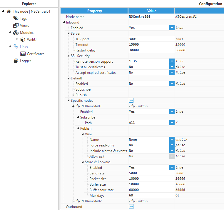
Figure 43. Configuration of central nodes to receive connections from other nodes.
Step 2: Configure N3Remote01 and N3Remote02 to provide data to the central servers (Config => Links).
- Provide the name (N3Remote01 and N3Remote02). This name must be unique among all connected nodes.
- Add the outbound connections to the central servers. The name of each outbound connection must match exactly with the name of the destination central server.
- Configure tag subscription as “None” since the remote nodes won’t be subscribed to the tags in the central nodes.
- Configure the Publish view as “Full model” in order to push all local events to the remote nodes.
- Configure the connection details, IP, and port, for the central servers.
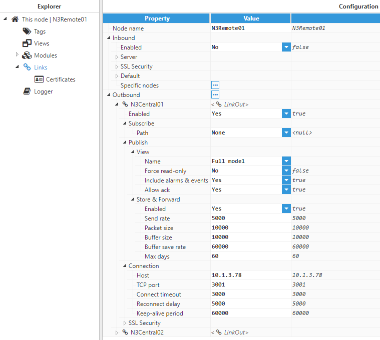
Figure 44. Outbound connections configuration for N3Remote01
Once the configuration of all nodes is complete, the remote nodes will send a digital certificate to the central servers. All certificates must be set as “trusted” in the central servers.
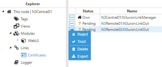
Figure 45. Digital certificates of the remote nodes in the central node
Once the digital certificates for the remote nodes have been “trusted” by the central server, the digital certificate from the central servers must also be “trusted” by the remote nodes.
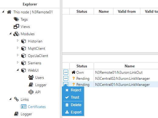
Figure 46. Digital certificates of the central nodes in the remote node
Once all digital certificates have been trusted, the connection has been successfully established and the link status will be displayed in Diagnostics => Links to show that these remote tags are now available in the central nodes.

Figure 47. Status of the links in the remote node
 Figure 48. Status of the links in the central node