The following steps show how to read data from a Modbus TCP server. This User Guide assumes a basic understanding of Modbus communication protocol.
Step 1: Create the module: (Config => Modules => button to the left of Modules => New module)
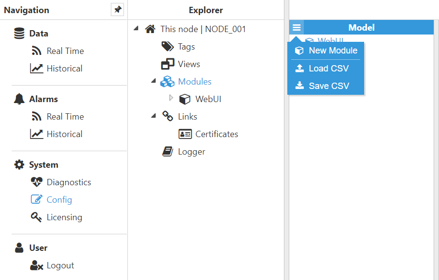
Figure 9. New module creation
Step 2: Provide a name for the module (in this case MbClient), assign the type of module (in this case ModbusClient) and save the new configuration.
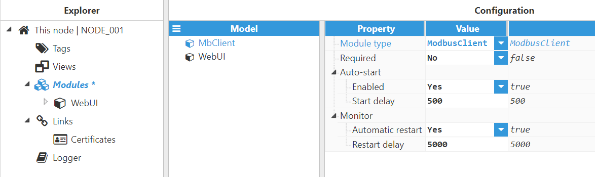
Figure 10. Configuring new module as ModbusClient
Step 3: Configure the log (usually the default values are sufficient). Save the log configuration.
.png)
Figure 11. Default log configuration
Step 4: Set up the Modbus channel. Each connection to a Modbus server is setup with a channel and a device. The channel represents the connection media (Ethernet or serial connection) and the device represents the Modbus server (or Modbus slave for serial connections). This means that in order to connect to a Modbus sever, a Modbus channel must be created and configured first, providing all the necessary communication settings.
.png)
Figure 12. New Modbus channel set up
Step 5: Set up the Modbus device. Save the Modbus driver configuration and restart the module once the device has been configured.
.png)
Figure 13. New Modbus device setup
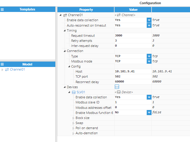 Figure 13-bis. New Modbus device setup
Step 6: Create a tag to connect through to the Modbus sever: Config => Tags => New Tag.
.png)
Figure 14. New tag generation
Step 7: Configure the tag. All details regarding the communication should be configured in Source entry:
- Source.Enabled: True
- Source.Module Type: ModbusClient
- Source.Module name: MbClient (the module created in previous steps)
- Source.Config.Device: Channel01/1 (the channel/device created in previous steps)
- Source.Config.Modbus Address: The Modbus address of the tag
- Source.Config.Data type: The Modbus data type
- Source.Config.Scan rate: The signal’s scan rate
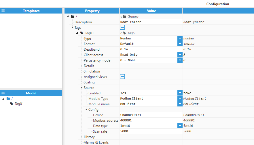
Figure 15. Configuration of tags belonging to Modbus devices
Step 8: The tag should now be available, displaying as good quality in the Real-Time display.
.png)
Figure 16. Tag value in real-time display