Note:
Before starting the configuration, a new module instance must be created. Click here for more information about creating Module instances.
Note:
This module is available from N3uron version 1.22.4.
Module Configuration
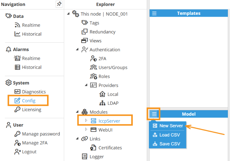
As shown in the screenshot to create a new Server follow these steps:
Navigate to System → Config → Modules → IccpServer, or the name provided to the IccpServer instance.
In the Model panel, click the menu (≡) and choose New Server to add additional IccpServer instances. You can also Load CSV to import or Save CSV to export a model configuration. Below is an explanation of the various configuration options.
Server Configuration
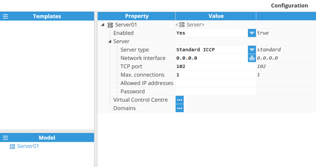
A server represents the physical medium to which one or more client devices can be linked. Each server requires the following settings to be configured.
Settings | Description |
Enabled | Enables or disables this ICCP/TASE.2 server instance. When disabled, the server will not be initialized or accept any client connections. |
Server |
Important: The combination of network interface and port must be available; otherwise, the server will fail to start due to a socket binding error.
The maximum configurable value is 100 connections.
If left empty, no password authentication is required. All passwords are encrypted for security reasons. |
Virtual Control Center Configuration
Once a Server has been configured, new data points can be added to Virtual Control Center. To create a new DataPoint, you can click on the 3-dotted icon → New DataPoint. Each DataPoint requires the following settings to be configured.
Settings | Description |
Tag | Select the N3uron tag associated with this data point. For indication types, this tag is the source whose value is exposed to ICCP clients. For command types, this tag is the destination that receives values when an ICCP client issues a command. |
Data type | Specifies the ICCP/TASE.2 data type for this data point. Indication types
How the source tag maps to a State value The source tag value is translated following the IEC 60870-5 double-point convention:
Suffixes (indications)
Command types
Each command type is available as Direct Operate (immediate execution) or Select Before Operate (SBO), (two-step confirmation). SBO commands require a checkback ID and a select timeout. |
Domains Configuration
Once a Server has been configured, new Domains can be added to Server. To create a new Domain, you can click on the 3-dotted icon → New Domain. You can also Load CSV or Save CSV to import or export the model configuration.

Once a Domain has been configured, new Bilateral Tables can be added to Domain. Each Bilateral Table requires the following settings to be configured.
Settings | Description |
Bilateral Table ID | Identifies this domain within the ICCP/TASE.2 bilateral agreement. This string uniquely identifies the bilateral table between two control centers and must match the value configured on the remote end. |
To create a new Data Point, you can click on the Data Points ellipsis button and select New DataPoint. Please refer to Data point Settings table in previous section for more information. To create a new Data Set, you can click on the Data Sets ellipsis button and select New DataSet. You can also Load CSV or Save CSV to import or export the model configuration.
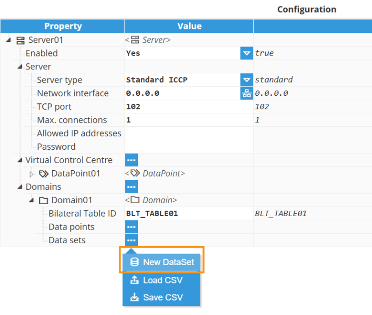
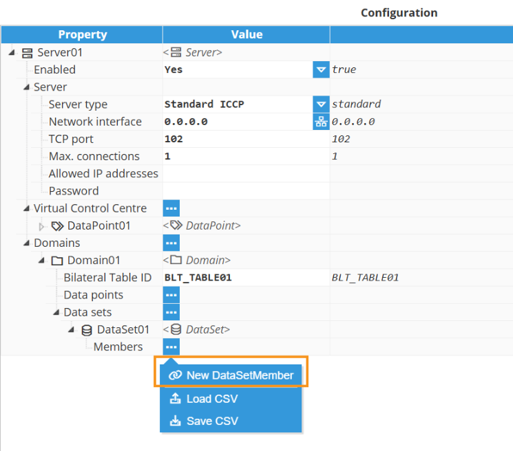
Once a Dataset has been configured, new Data Set Members can be added to Dataset. To create a new Member, you can click on the 3-dotted icon → New DataSetMember. You can also Load CSV or Save CSV to import or export the model configuration.
Note:
The Point Reference setting should be selected from VCC → Data Point or Domain → Data Point, so Data Points need to be created first based on the scope required for deployment.
Each DataSetMember requires the following settings to be configured.
Settings | Description |
Point reference | References a data point by its name. The referenced point can belong to any Domain or to the VCC. |